EasyManua.ls Logo

SAJ H2-6K-S3 - Communication Connection

SAJ H2-6K-S3
36 pages
Print Icon
To Next Page IconTo Next Page
To Previous Page IconTo Previous Page
Loading...
H2 Series
30
6.Make sure the DC switch is at OFF position
Figure 5.10
DC switch
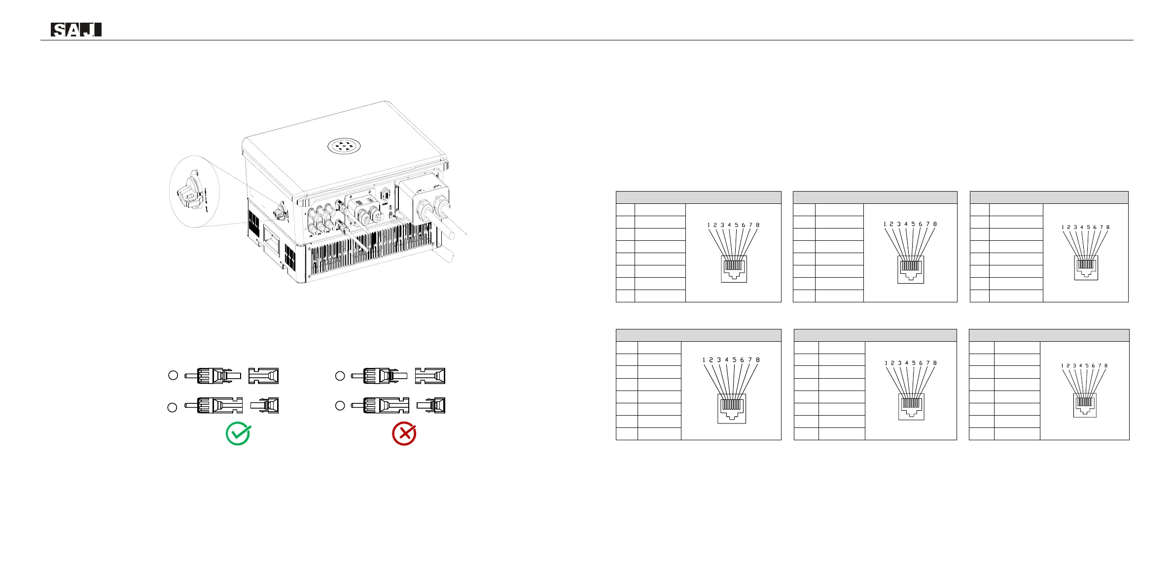
7.Connect the positive and negative connectors into positive and negative DC input terminals of the inverter,
a ā€œclickā€ should be heard or felt when the contact cable assembly is seated correctly.
Figure 5.11
Plug in PV connectors
5.4 Communication Connection
Note: 1) Confirm that the DC switch is OFF during installation to avoid short circuit caused by wrong
operation during battery wiring.
2) Please use the battery cable in original package.
EMS/METER
1
RS485-A+
2
RS485-B-
3
NC
4
NC
5
NC
6
NC
7
RS485-A+
8
RS485-B-
CT
1
R/CT.I+
2
R/CT.1-
3
NC
4
NC
5
NC
6
NC
7
NC
8
NC
DRM
1
DRM1/5
2
DRM2/6
3
DRM3/7
4
DRM4/8
5
RefGen
6
Com/DRM0
7
V+
8
V-
CAN/BMS
1
NC
2
NC
3
NC
4
CANH
5
CANL
6
NC
7
NC
8
NC
PORT0
1
NC
2
NC
3
NC
4
NC
5
NC
6
NC
7
NC
8
NC
PORT1
1
NC
2
NC
3
NC
4
NC
5
NC
6
NC
7
NC
8
NC
Thread the communication cable through the waterproof cable gland and connect to the corresponding port.
PV+
PV-
PV+
-
+
PV-
-
+

Related product manuals