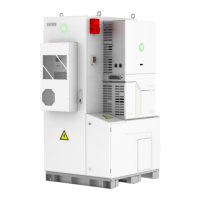
Step 5: After the battery modules installation, mark the proper positions of inverter and drill holes (10mm in
diameter, 65mm in depth) on those positions by using the inverter as a template. Remove the rubber feet for
the top battery module before installing inverter.
Figure 4.14
Drilling holes for installation of
Inverter
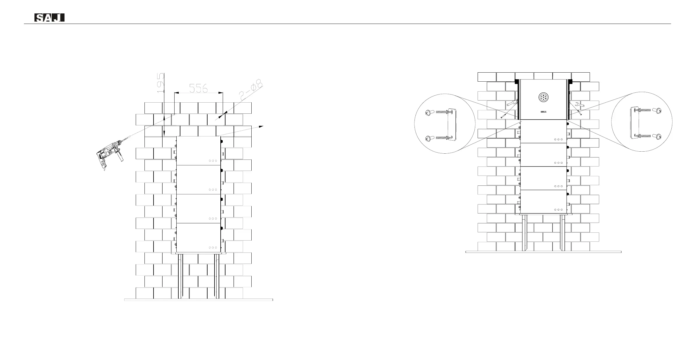
Step 6: Use a rubber hammer to drive the screw fixing seat into the holes to fix the bracket,use the wrench to
tighten the screws (M8*80 screw) to secure the inverter. Secure the locking bracket and inverter with screw
(M6*12).
Figure 4.15
Installing inverter
 Loading...