38 | EN SMARTY v2023.1
%\GHIDXOW'GLJLWDOLQSXWLVFRQ¿JXUHGDV6PRNHGHWHFWRULQSXWDQGVHWWR12LIQHHGHG1&FRQWDFWW\SHWKHQLWPXVWEHUHFRQ¿JXUHG6HH
section "ACCESSORIES SETUP (VERSION S300)".
8.4. EXTERNAL CO
2
/RH SENSORS (VERSION 1.1 / 1.2)
6PDUW\;36PDUW\;9XQLWVIHDWXUHWZRFRQQHFWLRQVIRUH[WHUQDO&2
2
/RH (input 0-10VDC) sensors.
Sensors connection:
+24VDC
AI4 (0-10V)
GND
12345678
AO1
GND
Vin
Transmiter 1
+24VDC
GND
123
AI1(0-10V)
Vin
GND
AO1
Transmitter 2
Smarty 3X V 1.1 and Smarty 4X V F2 1.1 come with the integrated RH sensor connected.
Smarty XP 1.2 / Smarty XV 1.2 units feature one connection for external CO
2
/RH (input 0-10VDC) sensors.
Sensors connection:
+24VDC
AI4 (0-10V)
GND
12345678
AO1
GND
Vin
Transmiter 1
These sensors feature 3 functions: Supply RH, Extract RH and Extract CO
2
.
Supply RH transmitter shall be installed inside supply air duct.
Extract RH and Extract CO
2
transmitters shall be installed inside extract air duct or room.
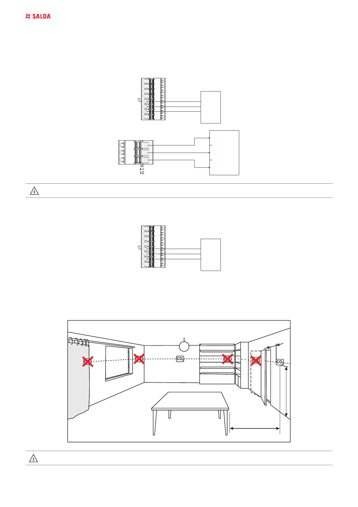
8.5. ROOM CO
2
TRANSMITTER INSTALLATION RECOMMENDATION
min. 50 cm
min. 60 cm
150 cm
max. 400m
2
If the duct CO
2
transmitter is used, it must be installed in the extract air duct. To install duct transmitters, hole drilling tools
are required .