16 | EN SMARTY v2023.1
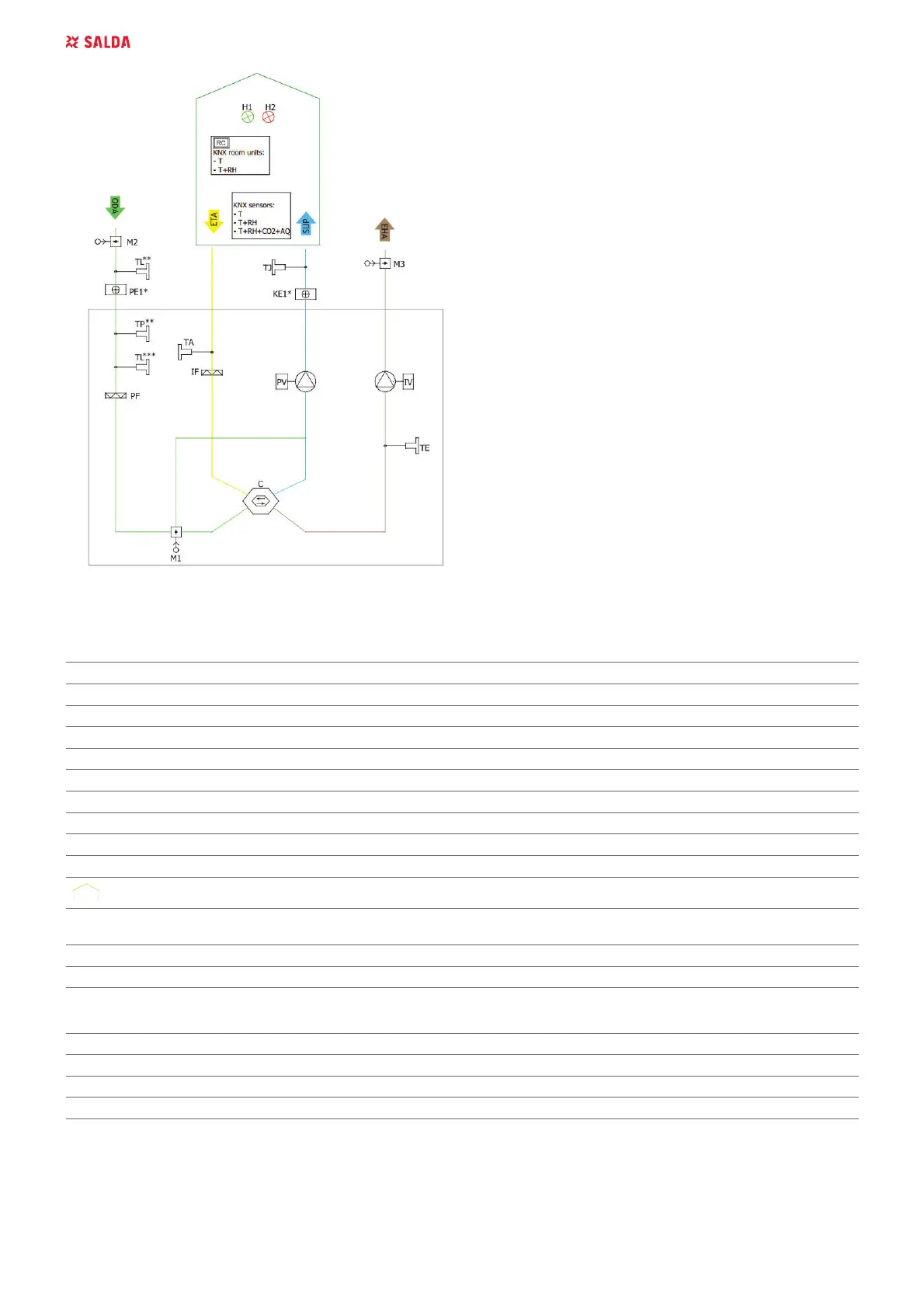
Figure 5.4.6. SMARTY XV S300 (* Only heater or preheater can be
connected at a time; ** Components connection only with PE1;
*** Components connection only without PE1)
THE LIST OF COMPONENTS
C Plate heat exchanger PV Supply air fan
IF ([WUDFWDLU¿OWHU PF 6XSSO\DLU¿OWHU
IV Exhaust fan TA Extract air temperature sensor
TE Exhaust air temperature sensor TJ Supply air temperature sensor
DTJ Extract air temperature and humidity sensor* CO
2
CO
2
sensor*
RH Air humidity sensor* PC Computer*
KE1 Electric heater PE1 Electric pre-heater
M1 By-pass damper M2 Outdoor air damper actuator
M3 Exhaust air damper actuator SK1 Supply air pressure sensor*
SK2 Exhaust air pressure sensor* TL Outdoor air temperature sensor
Ventilated premises MB-Gateway 1HWZRUNPRGXOH
NET 1HWZRUN RC
Stouch, ST-SA-Control, POS8.4420 or POS8.4440
remote control panel*
TP Air temperature after preheating coil sensor* AQ Air quality sensor*
T Temperature sensor*
* Component/possibility to connect it depends on model.
POSSIBLE PCB INPUTS/OUTPUTS
FA Fire alarm FPP Fireplace protection
H1 Operation/Working indication output H2 Alarm indication output
6\VWHPPRGHVZLWFK )DQVVSHHGVZLWFK
5.5. MOUNTING
• ,QVWDOODWLRQVKRXOGEHFDUULHGRXWE\TXDOL¿HGDQGWUDLQHGVWDႇRQO\
• When connecting air ducts, consider the labels on the casing of the unit.
• Before connecting to the air duct system, the connection openings of ventilation unit should be closed.
• :KHQFRQQHFWLQJWKHGXFWVWKHDLUÀRZGLUHFWLRQLQGLFDWHGRQWKHGHYLFHKRXVLQJVKRXOGEHREVHUYHG