68
9. ANNEXES.
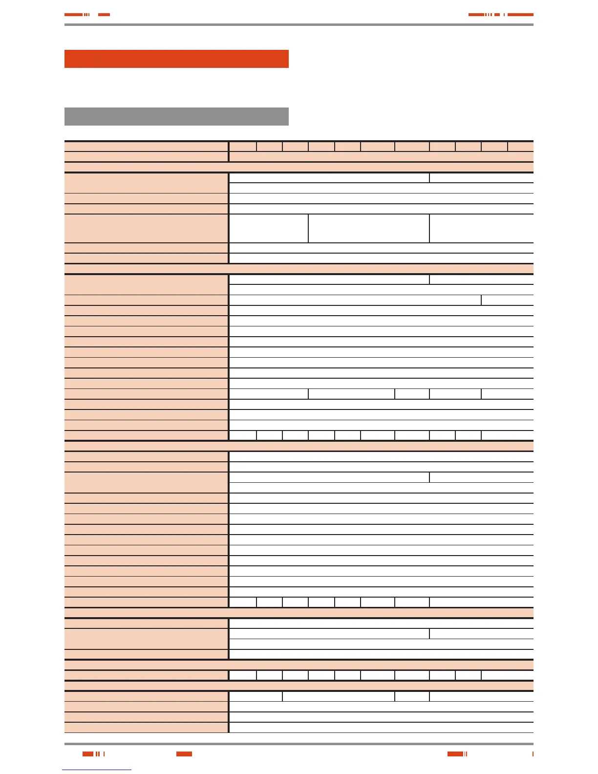
9.1. PARTICULAR SPECIFICATIONS, EQUIPMENTS (LV).
Nominal power (kVA) 5 7,5 10 15 20 30 40 50 60 80 100
Nominal power (kW) Depending on the input/output setting and power supply voltage (See chart 9)
INPUT
Nominal voltage
Single phase 115V, 120V, 127V or 133V -
Three phase 3x200V, 3x208V, 3x220V or 3x230V (4 wires: 3 phases+ N)
Input voltage range + 15% / –20%
Frequency 50 or 60 Hz ±5 %.
Total input current distortion
(depending on the quality of input mains)
100 % load: THD-i < 1.5 %
50 % load: THD-i < 2.5 %
10 % load: THD-i < 6.0 %
100 % load: THD-i < 1.0 %
50 % load: THD-i < 2.0 %
10 % load: THD-i < 5.0 %
100 % load: THD-i < 1.5 %
50 % load: THD-i < 2.0 %
10 % load: THD-i < 6.0 %
Current limit High overload: PFC limit (discharging batteries)
Power factor 0.99 from 10% load
INVERTER
Output nominal voltage
Single phase 115V, 120V, 127V or 133V -
Three phase 3x200V, 3x208V, 3x220V or 3x230V (4 wires: 3 phases + N)
(*) Output power factor 0.9 for three phase/three phase setting. 0.8 for L, M and N settings 0.8
Accuracy Static: ±1 %. Dynamic: ±2 % (step loads 100-0-100 %)
Output frequency 50 or 60 Hz synchronised ±5 Hz. Free running±0.05 %
Maximum slew rate ±1 Hz/s
Output wave shape Sinewave
Total output voltage harmonic distortion Linear load: THD-v < 0.5 %. Ref. non-linear load (EN-62040-3): THD-v < 1.5 %
Phase shifting 120 ±1 % (balanced load). 120 ±2 % (unbalanced load of 50 % )
Dynamic response time 10 ms. till 98 % of the static value
(**) Permissible overload 125 % for 10 min., >125.. 135 % for 5 min., >135.. 150 % for 1 min., > 150 % for 20 ms.
Permissible crest factor 3.4 to 1 3.2 to 1 2.8 to 1 3.2 to 1 3 to 1
Permissible power factor 0.7 leading to 0.7 lagging
Unbalanced output voltage (100 % unbalanced load) < 1 %
Current limit High overload, short-circuit: RMS voltage limit. High current crest factor: Peak voltage limit
Efficiency on battery mode (100% linear load) (%) 94.3 94.6 94.8 95.3 95.6 95.9 96.4 96.1 95.9 96.4
STATIC BYPASS
Type Solid state(SCR)
Bypass line Common. Separate as an option (B)
Nominal voltage
Single phase 115V, 120V, 127V or 133V -
Three phase 3x200V, 3x208V, 3x220V or 3x230V (4 wires: 3 phases + N)
Voltage range Preset +12 % (adjustable between +20... +5%) / –15% (adjustable between –25... –5%
Voltage hysteresis ±2 % as regards the bypass voltage range. In a standard equipment is +10 /–13%
Frequency 50 or 60 Hz
Frequency range ±5 Hz (selectable between 0.5 - 1.0 - 2 and 5.0 Hz)
Frequency hysteresis 1 Hz as regards the frequency range (selectable among 0.2 - 0.5 - 1.0 and 2.0 Hz)
Activation criteria Controlled by microprocessor
Transference time Nil, less in Smart Eco-mode < 3ms
Permissible overload 400 % for 10 s
Transference to bypass Immediately, for overloads over 150 %
Re-transference Automatic after alarm cancelling
Efficiency on Smart Eco-mode 95.0 95.5 96.0 97.4 97.8 98.0 98.4 98.0
MANUAL BYPASS (MAINTENANCE)
Type Make before break
Nominal voltage
Single phase 115V, 120V, 127V or 133V -
Three phase 3x200V, 3x208V, 3x220V or 3x230V (4 wires: 3 phases + N)
Frequency 50 or 60 Hz
GENERAL
Total efficiency (100% linear load) (%) 89 89.5 90 91 91.5 92 93 92.5 92 93.0
BATTERIES
Quantity 38 36 40 36
(***) Type Pb Ca
Floating voltage per battery 13.65 V at 20ºC
Compensation of the battery floating voltage Adjustable (preset to –18 mV/ºC)
USER MANUAL