69
SALICRU
Nominal power (kVA) 5 7,5 10 15 20 30 40 50 60 80 100
Nominal power (kW) Depending on the input/output setting and power supply voltage (See chart 9)
Capacity (Ah) 7 12 18 26
Standard charging current (Cx0,2) (A) 1.4 2.4 3.6 5.2
Battery terminal torque According to battery manufacturer
Fitted in the same UPS cabinet YES NO
DIMENSIONS AND WEIGHTS FOR UPS CONFIGURATIONS WITH STANDARD BACK UP TIME
Quantity of cabinets 1 (UPS + batteries) 1 (UPS) / 1 (batteries)
Maximum
dimensions(mm)
(Depth x Width x
Height)
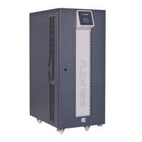
CUBE3+ / CUBE3+ B1
770x450x1100
875x590x1320 850x900x1900
CUBE3+ B / CUBE3+ B B1
875x590x1320
875x870x1320 850x1225x1900
Batteries -
770x450x1100
1050x650x1320 850x1300x1900
Casters without brake. Equipment / batteries YES / - YES / YES YES / NO NO / NO
Cabinet weight (kg)
CUBE3+ B1 100 102 105 150 175 - - - - - -
CUBE3+ B B1 102 104 107 153 178 - - - - - -
CUBE3+ 210 212 215 310 400 185 265 290 290 540 550
CUBE3+ B 212 214 217 313 403 190 275 310 310 570 580
External batteries - - - - - 510 1020 1020 1020 1655 1690
Tabla 7. Technical specifications for equipments with (LV) voltages.
9.2. TECHNICAL SPECIFICATIONS, EQUIPMENTS (HV).
Nominal power (kVA) 7,5 10 15 20 30 40 50 60 80 100 120 160 200
Nominal power (kW) Depending on the input/output setting and power supply voltage (See chart 9)
INPUT
Nominal voltage
Single phase 220V, 230V or 240V -
Three phase 3x380V, 3x400V or 3x415V (4 wires: 3 phases + N)
Input voltage range + 15% / –20%
Frequency 50 or 60 Hz ±5 %
Total input current distortion
(depending on the quality of input mains)
100 % load: THD-i < 1.5 %
50 % load: THD-i < 2.5 %
10 % load: THD-i < 6.0 %
100 % load: THD-i < 1.0 %
50 % load: THD-i < 2.0 %
10 % load: THD-i < 5.0 %
100 % load: THD-i < 1.5 %
50 % load: THD-i < 2.0 %
10 % load: THD-i < 6.0 %
Current limit High overload: PFC limit (discharging batteries)
Power factor 0.99 from 10% load
INVERTER
Output nominal voltage
Single phase 220V, 230V or 240V -
Three phase 3x380V, 3x400V or 3x415V (4 wires: 3 phases + N)
(*) Output power factor 0.9 for three phase/three phase setting. 0.8 for L, M and N settings 0.8
Accuracy Static: ±1 %. Dynamic: ±2 % (step loads 100-0-100 %)
Output frequency 50 or 60 Hz synchronised ±5 Hz. Free running ±0.05 %
Maximum slew rate ±1 Hz/s
Output wave shape Sinewave
Total output voltage harmonic distortion Linear load: THD-v < 0.5 %. Ref. non-linear load (EN-62040-3): THD-v < 1.5 %
Phase shifting 120 ±1 % (balanced load). 120 ±2 % (unbalanced load of 50 % )
Dynamic response time 10 ms. at 98 % of the static value
(**) Permissible overload 125 % for 10 min., >125.. 135 % for 5 min., >135.. 150 % for 1 min., > 150 % for 20 ms.
Permissible crest factor 3.4 to 1 3.2 to 1 2.8 to 1 3.2 to 1 3 to 1
Permissible power factor 0.7 leading to 0.7 lagging
Unbalanced output voltage (100 % unbalanced load) < 1 %
Current limit High overload, short-circuit: RMS voltage limit. High current crest factor: Peak voltage limit
Efficiency on battery mode (100% linear load) (%) 94.3 94.5 95.0 95.3 95.9 96.2 96.3 96.4 96.9 96.5 96.4 96.8 96.9
STATIC BYPASS
Type Solid state
Bypass line Common. Separate as an option (B)
Nominal voltage
Single phase 220V, 230V or 240V -
Three phase 3x380V, 3x400V or 3x415V (4 wires: 3 phases + N)
Voltage range Preset +12 % (adjustable between +20... +5%) / –15% (adjustable between –25... –5%
Voltage hysteresis ±2 % as regards to bypass voltage range. In a standard equipment is of +10 /–13%
Frequency 50 or 60 Hz
Frequency range ±5 Hz (selectable among 0.5 - 1.0 - 2 and 5.0 Hz)
Frequency hysteresis 1 Hz as regards the frequency range (selectable among 0.2 - 0.5 - 1.0 and 2.0 Hz)
Activation criteria Controlled by microprocessor
Transference time Nil, less in Smart Eco-mode < 3ms
 Loading...