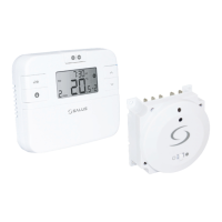
RT500RF INSTRUCTION MANUAL
7
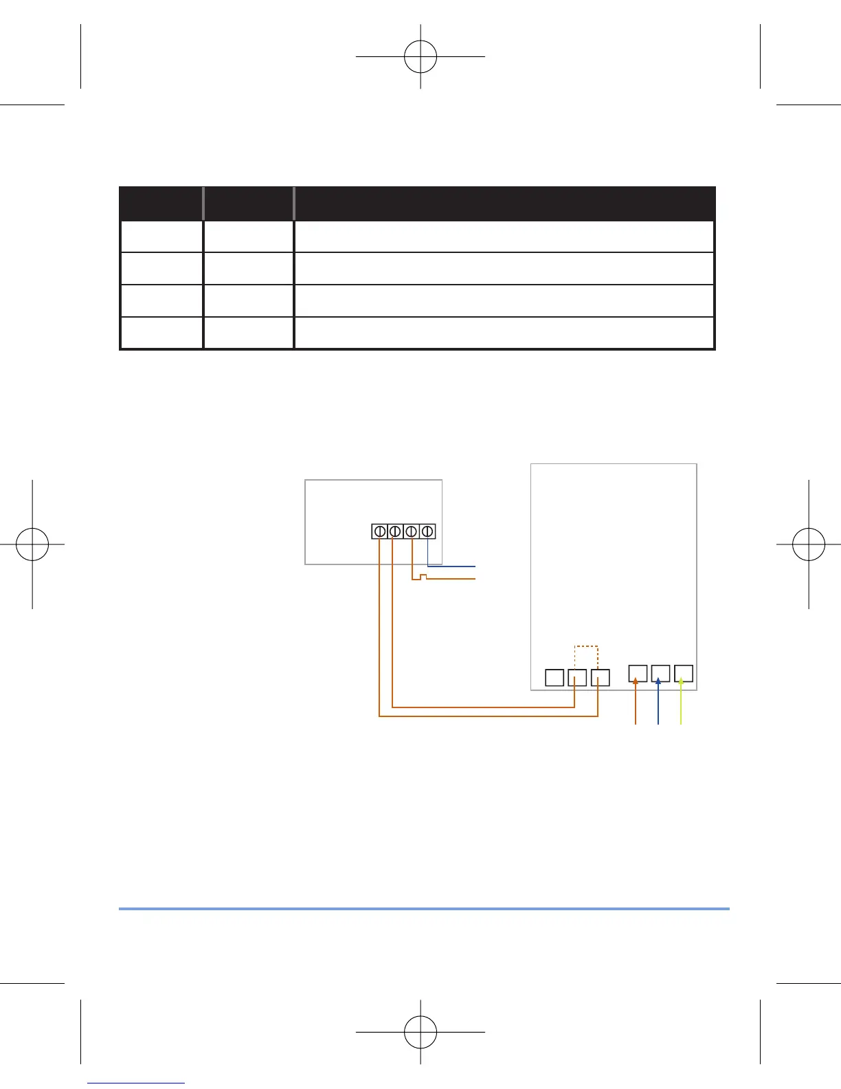
RECEIVER WIRING TERMINALS
Terminal Identifier Description
1 NO Normally Open [N/O]
2 COM Linked Live feed (230V AC heating applications only)
3 L Live feed (230V AC)
4 N Neutral
TYPICAL WIRING INSTALLATIONS
a.230V AC Installation
Notes:
• Receiver unit should have a permanent 230V AC main supply
• Confirm that the Boiler has an external thermostat loop and
is configured for 230V switching
• If the boiler has two terminals for the thermostat, remove the
link from the boiler