CONNECTION OF THE CONTROL UNIT AND OF THE FLUID PART
The CYCLOMIX
TM
MICRO must be
connected to a dry and clean
compressed air (minimum 4 bar / 58 psi)
and to a single phase electric supply
(115 V / 230V) connected to an isolating
switch. The network ground will be
connected in the control bay on a contact
one of the CYCLOMIX
TM
MICRO
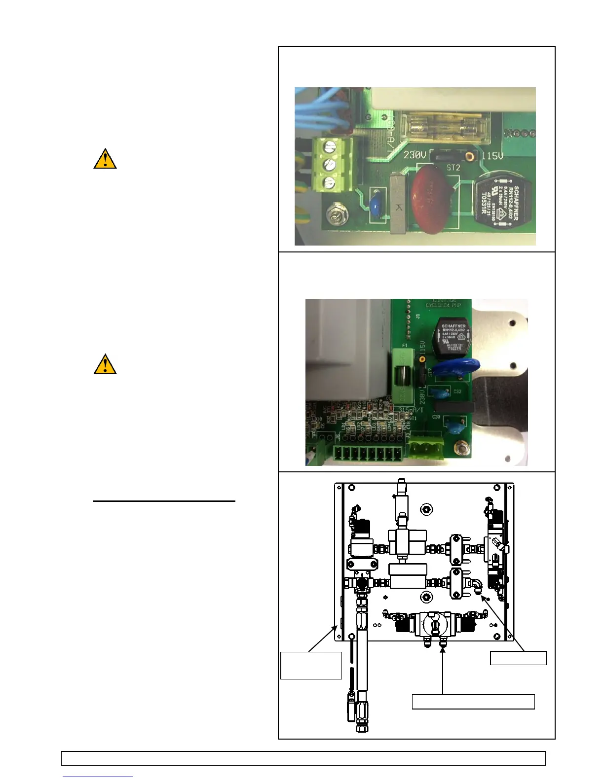
If no, open the electric box removing the
protective housing (10) and shift the
staple (230V 115V).
The air connection of the CYCLOMIX
TM
is Female 1/4 G (air inlet = R1
and air outlet = R2).
The connection between the control unit
and the fluid module is carried out via
provided cable, length 5 m / 196.85 ft
For lengths up to 5 m / 196.85 ft
the cables between them (male-female).
The connection between the two
cables must not be in the explosive area.
A valve fitted with fittings is supplied with
. It will be
mounted on the gun air inlet : it enables
to shut off quickly the fan air (priming,
flushing stage).
Fuse 160 mA
for CYCLOMIX
TM
MICRO
with serial number < to 09Y1080
Fuse 315 Ma
for CYCLOMIX
TM
MICRO
with serial number >to 09Y1080
Connection of the fluid inlets :
The fluid inlets are M 1/2 JIC.
We advice you to install AIRMIX
filters on the fluid inlets (catalyst and
The base(s) and the base solvent are
connected on the color changer installed
on the CYCLOMIX
TM
MICRO.
The catalyst is connected :
-
directly on the elbow installed before
or on the color changer (cata and cata
solvent) installed in the CYCLOMIX
TM
It depends upon the configuration of the
The air connection is made on the two
SAMES KREMLIN Page 14 Manual : 573.191.112