12
2
GENERAL DESCRIPTION OF PV / SOLAR SYSTEM
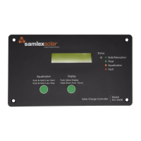
Bypass Diodes
As mentioned, PV / Solar cells are wired in series and in parallel to form a PV / Solar
Panel (Module). The number of series cells indicates the voltage of the Panel (Module),
whereas the number of parallel cells indicates the current. If many cells are connected
in series, shading of individual cells can lead to the destruction of the shaded cell or of
the lamination material, so the Panel (Module) may blister and burst. To avoid such an
operational condition, Bypass Diodes are connected anti-parallel to the solar cells as in
Fig. 2.7. As a consequence, larger voltage differences cannot arise in the reverse-current
direction of the solar cells. In practice, it is sufcient to connect one bypass diode for
every 15-20 cells. Bypass diodes also allow current to ow through the PV module when
it is partially shaded, even if at a reduced voltage and power. Bypass diodes do not cause
any losses, because under normal operation, current does not ow through them.
+-
load
bypass diodes
A K
Figure 2.7: Parallel PV cell with bypass diodes
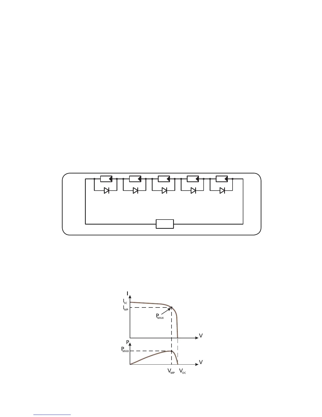
Current (I), Voltage (V) and Power (P) Curves of a PV / Solar
Panel (Module) and how the PV / Solar Panel (Module) is rated -
V
oc
, Vmp , I
sc ,
Imp , Pmax
Fig. 2.8 Current (I), Voltage (V) and Power (P) Curves