35
6
INSTALLATION & OPERATION
25 mm
25 mm
25 mm
25 mm
25 mm
25 mm 25 mm
25 mm
6 mm
6 mm
6 mm
6 mm
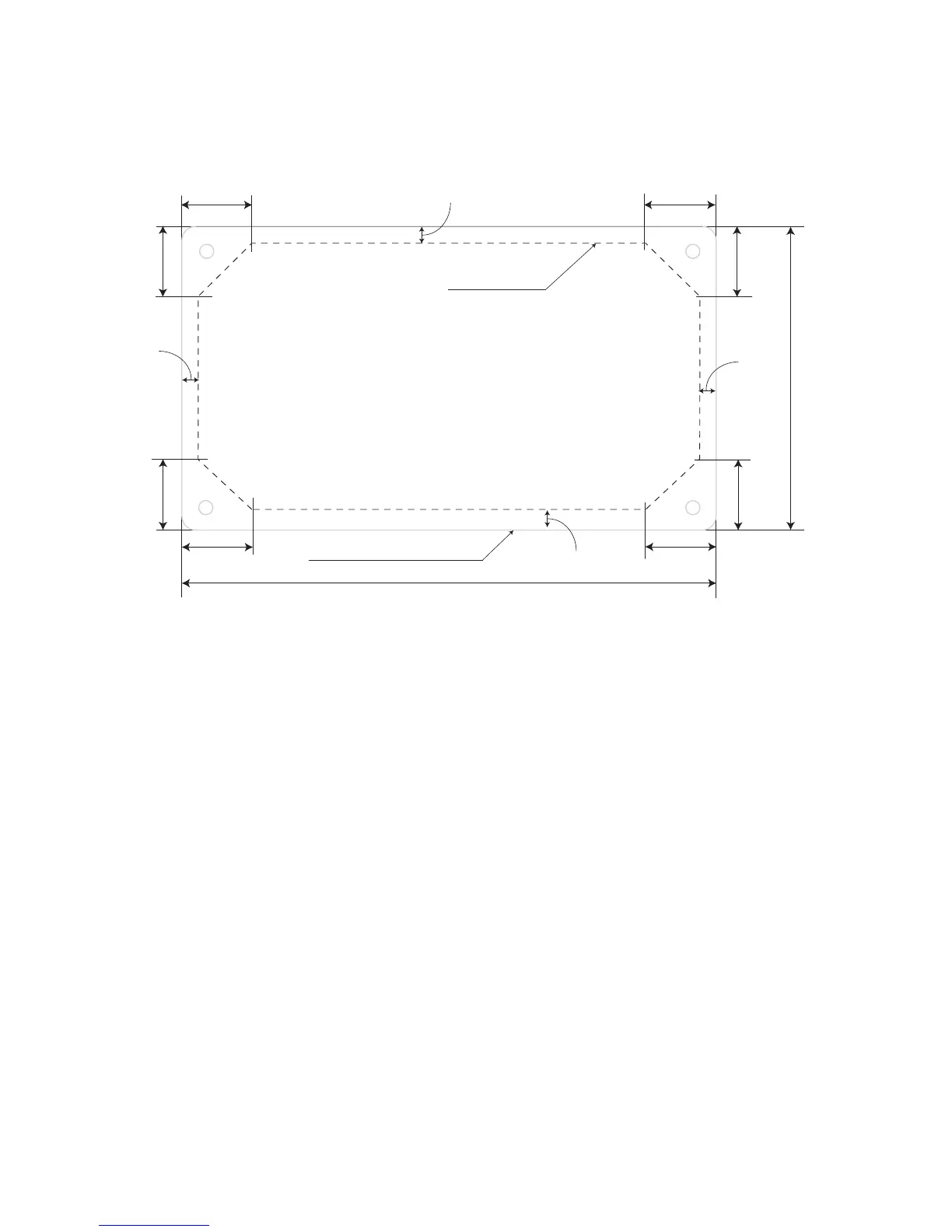
190 mm
108 mm
- Cut the wall / panel along the dotted line
with a jig saw.
- This will create a pocket in the wall / panel
for ush mounting of Charge Controller SCC-30AB.
Outline of the front panel
Fig. 6.1. Drawing for making the cut-out in the wall / panel
2. Make sure the PV currents will not exceed the ratings of the SCC-30AB.
3. The connections to the SCC-30AB terminals are shown in the drawing at Fig. 5.2.
A barrier type of Terminal Strip has been provided for connecting the PV array and
the battery. M-4 screws with clamping washers are used to make the connection. A
at or a #2 Philips head screw driver may be used to tighten these screws. Tighten
each terminal clamping screw to 20 inch-pounds of torque. The distance between the
barriers is 9 mm and a standard Spade Type of terminal lug meant for # 8 Stud and
AWG #10 – AWG #12 wire may be used at the end of the wires to be connected to
these terminals. 4 such terminal lugs are provided with the unit for ease of installation
4. Set the DIP Switch 1 for the voltage system, set the DIP Switch 2, 3, 4 for battery
charging algorithm.
5. Connect the BATTERY rst. Be careful that bare wires do not touch the metal case
of the controller.
• The BATTERY must be connected before the Solar Panel (Module)/Array to
properly start the microcontroller, activate protections & guide installation.
• A battery below 9 volts may not start the microcontroller properly. Make sure the
battery is charged before installing the system.