EB 2520 EN 15
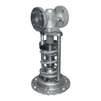
Design and principle of operation
Dimensions and weights
Table2providesasummaryofthedimensionsandweights.Thelengthsandheightsinthe
dimensionaldrawingsareshownonpage17.
Table1: Technical data
Valve size DN15 DN20 DN25 DN32 DN40 DN50
Pressure rating (valve) PN16·PN25·PN40
K
VS
coefcients
Standard
4.0
6.3
8.0
16 20 32
Reduced K
VS
coefcients
0.016·
0.04·0.1·
0.25·0.4·
1.0·1.6·
2.5
0.016·
0.04·0.1·
0.25·0.4·
1.0·1.6·
2.5·4.0
0.016·
0.04·0.1·
0.25·0.4·
1.0·1.6·
2.5·4.0·
6.3
1.6·2.5·
4.0·6.3·
8.0
1.6·2.5·
4.0·6.3·
8.0·16
1.6·2.5·
4.0·6.3·
8.0·16·
20
Max. perm. differential pressure 10bar·12bar
1)
Max. permissible temperature
range (medium temperature)
–20to+60°C(0to+150°C)
2)
Leakageclassacc.toIEC60534-4 Soft-seated,minimumClassIV
Conformity
· ·
Set point ranges
5to15mbar
5)
·10to30mbar
5)
·25to60mbar
5)
·
50to200mbar·0.1to0.6bar·0.2to1bar·0.8to2.5bar·
2to5bar·4.5 to10bar
Max. perm.
pressure at
operating
diaphragm
1200cm² 0.5bar
640cm² 1bar
320cm² 2bar·10bar
3)
160cm² 3bar·16bar
3)
80cm² 5bar·16bar
3)
40cm²(2to5bar) 10bar·16bar
3)
40cm²
4.5to10bar
15bar·16bar
3)
Pressure
balancing
K
VS
=0.016to4 Without balancing diaphragm
K
VS
=6.3to32 With balancing diaphragm
Pressure tapping External
4)
Controllineconnection G¼
1)
Versionwithsetpointsfrom0.1to10bar
2)
For unbalanced versions with FKM diaphragm and FKM soft seal
3)
Versionwithforcelimiter
4)
Specialversionwithpressuretappingdirectlyatthevalve(seesection3.1)
5)
The set point range cannot be combined with the following K
VS
coefcients:16·20·32