18 EB 3136 EN
Mounting and start-up
5.4 Electrical connection
Î See Fig.5 and Fig.2
Upon installation of the electric cables, you
are required to observe the regulations con-
cerning power installations according to
DINVDE0100 as well as the regulations of
your local power supplier.
Use a suitable power supply which guaran-
tees that no dangerous voltages reach the
device in normal operation or in the event of
a fault in the system or any other system
parts.
Connect the actuator to the electrical network
only after the power supply is rst switched
off. Make sure the power cannot be switched
on unintentionally.
A power supply of 230V (10%) or 24V
(10%), 50Hz is required (uEB5857 for
more details).
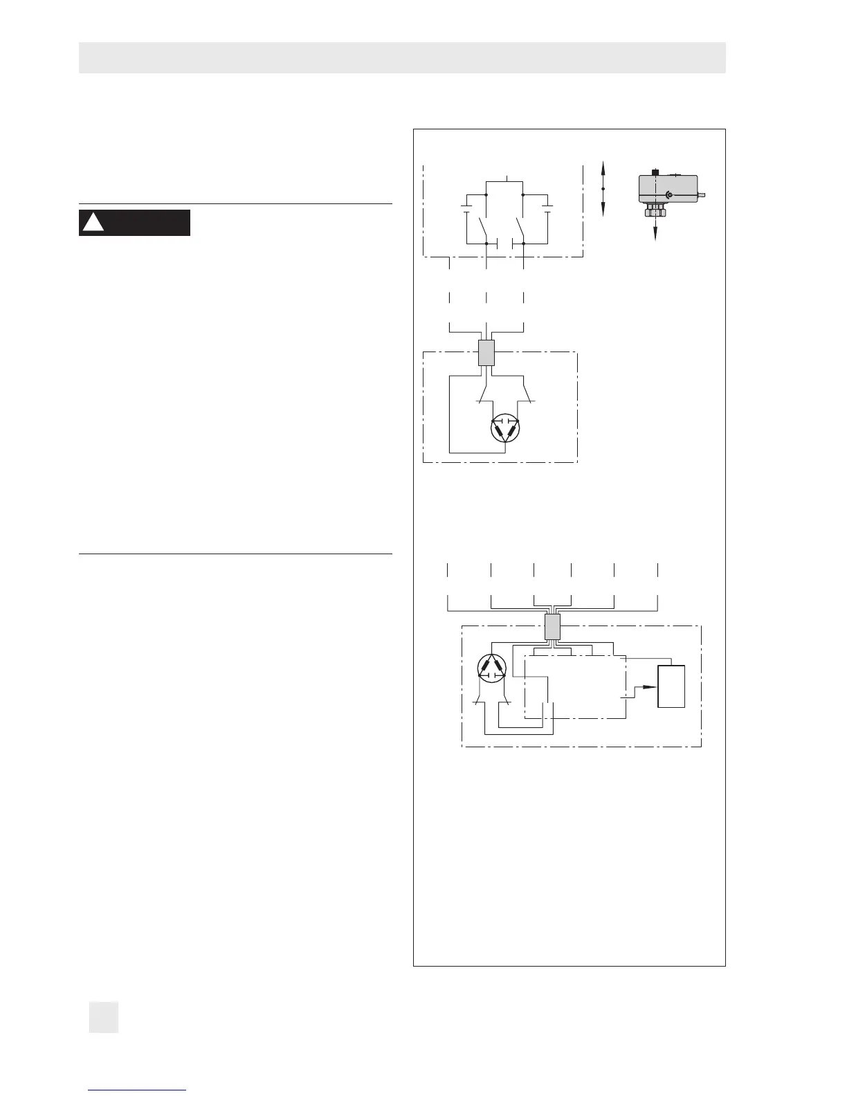
Î Connect the electric actuator using the
three-wire connecting cable (see Fig.5).
If voltage is applied to the white and
green wires, the actuator motor retracts
the actuator stem (18). The restriction
stem (12) is pushed upward by the
spring (15), causing the ow rate to rise.
In contrast, a control signal applied to
the white and brown wires causes the ac-
tuator stem to extend. The restriction stem
(12) is pushed downward by the spring
(15), causing a lower ow rate.
WARNING
!
Three-step version
BNWH GN
aL eL
BN BK YE GN RD OG
24 V, 50 Hz 0...10 V 0...10 V
_
+
_
+
NL
eL Actuator stem retracts
aL Actuator stem extends
Note: The interference suppression capacitors
Ce in the output circuit of the connected control-
ler must not exceed a value of 2.5nF to ensure
the proper functioning of the actuator.
Fig.5: Electrical connection