EB 3136 EN 9
Design and principle of operation
3 Design and principle of oper-
ation
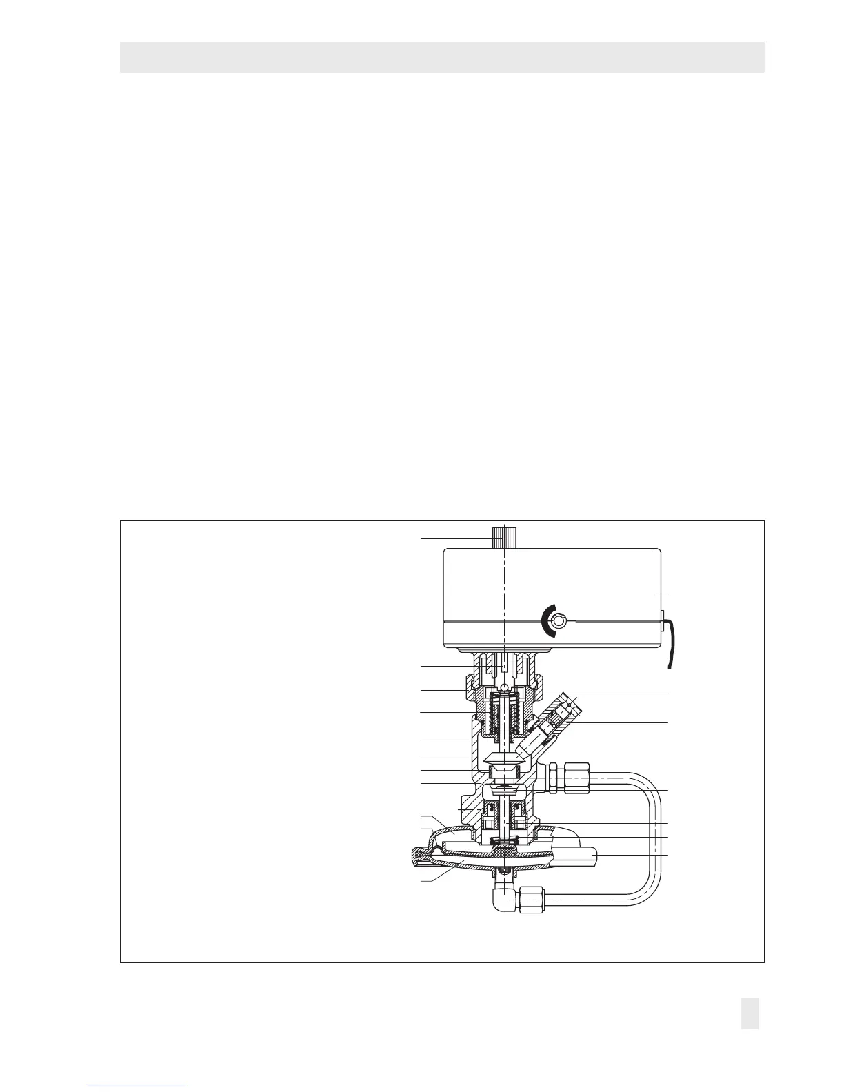
Î Refer to Fig.2
The pressure-independent control valve
(PICV) consists of the Type2488N Flow
Regulator and the Type5857 Electric Actua-
tor. The valve is tted with a connecting
piece for connection of an electric actuator.
As a result, it is possible to transmit the con-
trol signal of an electric control device to
achieve additional temperature control by
changing the restriction position. The medi-
um ows through the valve in the direction
indicated by the arrow on the valve body.
The ow rate is determined by the area re-
leased by the valve plug (3) and the adjust-
able restriction (11).
The installed positioning spring (5) deter-
mines the differential pressure across the re-
striction of 0.2bar. The pressure upstream of
the restriction (11) is transmitted over the
control line (7) to the upstream pressure side
of the actuator. The pressure downstream of
the restriction acts on the low-pressure side
of the operating diaphragm (9) through a
hole in the valve plug. The differential pres-
sure generated at the restriction is converted
into a positioning force by the operating dia-
phragm. This force is used to move the valve
plug depending on the force of the position-
ing spring (5). The ow rate is adjusted at
the set point screw (13).
1 Valve body
2 Seat
3 Plug
4 Plug stem
5 Positioning spring
6 Diaphragm actuator
7 Control line for upstream pressure
8 Upstream side
9 Operating diaphragm
10 Downstream side
11 Restriction
12 Restriction stem
13 Set point screw for ow control
14 Connecting piece
15 Spring
16 Type5857 Electric Actuator
17 Coupling nut
(max. 20Nm tightening torque)
18 Actuator stem
19 Manual adjuster
1
11