EB 5866 EN 3-1
Design and principle of operation
3 Design and principle of oper-
ation
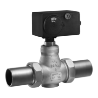
The medium ows through the single-seated
globe valve in the direction indicated by the
arrow. The position of the plug determines
the ow rate across the area released be-
tween plug (1) and seat (5). The valve is
opened by the valve spring when the actua-
tor stem retracts. The plug is moved by
changing the control signal applied to the
actuator. The valve and actuator have a
force-locking connection.
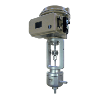
A special version (see Fig.3-3) is available
for water above 150°C and steam.
3.1 Fail-safe action
When the Type3222 Valve is combined with
one of the following actuators, the valve
moves to the fail-safe position upon failure of
the air supply or supply voltage:
− Type5825, Type5827-A and
Type5827-E Electric Actuators
− TROVIS5725-3 and TROVIS5725-8
Electric Actuators with Process Controller
− Type2780 Pneumatic Actuator
One of two different fail-safe positions can
be assumed by the control valve:
− Actuator stem extends: upon supply volt-
age or air supply failure, the actuator
stem extends.
The TROVIS5725-3 and TROVIS5725-8
Electric Actuators with Process Controller in
the version with force-locking attachment
and the Type5827-A and Type5825
Electric Actuators with "actuator stem
extends" fail-safe action are tested by the
German technical surveillance association
TÜV according to DINEN14597 in
combination with the SAMSON Type3222
Valve. The registration number is available
on request.
− Actuator stem retracts: upon supply volt-
age or air supply failure, the actuator
stem retracts.
The fail-safe action of pneumatic actuators
can be reversed (see associated actuator
documentation). The fail-safe action of elec-
tric actuators (with process controller) is al-
ready determined at the ordering stage.
Note
Note
 Loading...