EB 8331-3 EN 5-5
Installation
Actuating shaft
Fig.5-6: Actuating shaft for manual override
(actuator for attachment with ring
nut)
For actuators with "actuator stem extends"
fail-safe action, the supply voltage must be
applied to allow the actuator stem be retract-
ed. To apply the supply voltage, proceed as
described in section5.6.
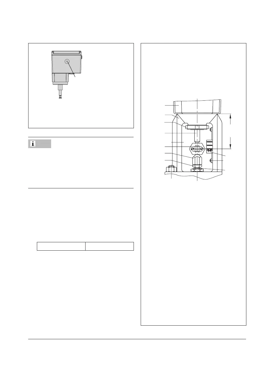
4. Place actuator onto the valve bonnet
(2.3) and secure using the ring nut (7).
5. When the stem connector nut (8) rests on
the actuator stem (3), attach both stem
connector clamps (4) and fasten with
screws.
Tightening torque 150Nm
6. Move the actuator stem (3) to the end
position (valve closed) as described in
the 'Operation' section.
7. Align travel indicator scale (10) with the
middle of the stem connector (4) and
screw tight.
Note
Types3374-15/-17/-26/-36
Connection with ring nut (formA)
AttachmenttoSeries240Valves
1
7
3
4
8
9
5
1 Actuator
2.3 Bonnet
3 Actuator stem
4 Stem connector
5 Plug stem
7 Ring nut
8 Stem connector nut
9 Lock nut
10 Travel indicator scale
Fig.5-7: Attachment to Series240 Valves