EB 8331-3 EN 5-11
Installation
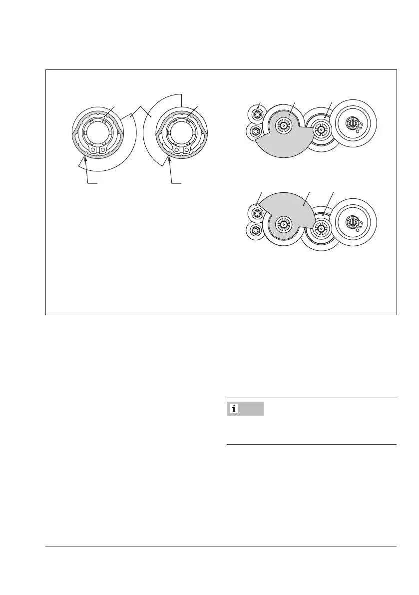
1 Intermediate gear
18 Adjustment gear
19 Contactcam
20 Cam holder
21 Contact cam
B
B
When actuator stem retracted
When actuator stem extended
Fig.5-13: Contact cams and cam holder
Actuator stem re-
tracted
Actuator stem
extended
19 1920
Fig.5-14: Contact cam unit
Actuators with resistance transmitters
1. Unscrew screws on housing cover and
take the cover off the actuator.
2. Move the actuator stem to the end posi-
tion depending on the fail-safe action
"actuator stem extends" or "actuator
stem retracts” (see the 'Operation' sec-
tion).
3. Remove serrated ring (6) and shim (10)
fromspindle2(11.2).SeeFig.5-15.
4. Continueasdescribedinitem5-9on
page8.
The basic unit is not required for the version
with resistance transmitter.
Note