3-10 EB 3018 EN
Design and principle of operation
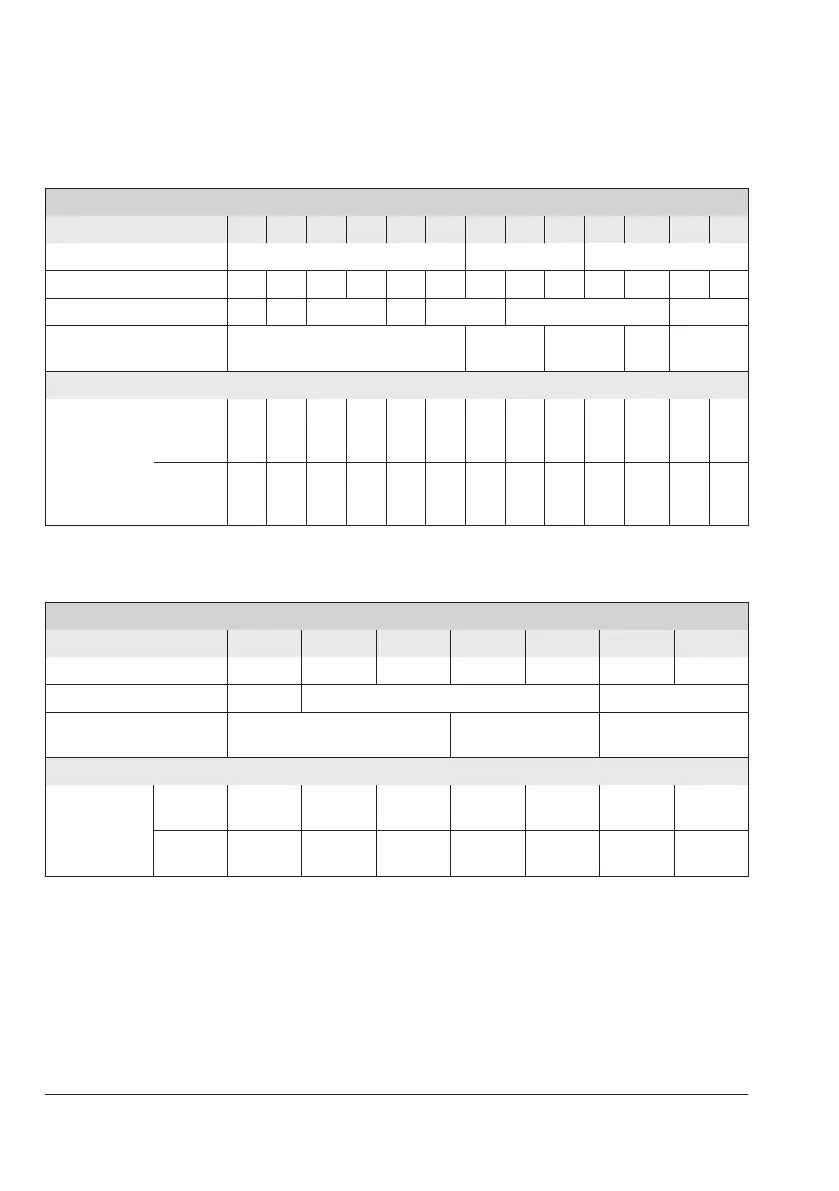
Table 3-4: K
VS
coefcients, x
FZ
values, ow rate set point ranges for water and max. per-
missible differential pressures (valve balanced by a bellows)
Type2423E Valve balanced by a bellows
Valve size DN 15 20 25 32 40 50 65 80 100 125 150 200 250
Valve travel 10mm 16mm 22mm
K
VS
coefcient 4 6.3 8 16 20 32 50 80 125 190 280 420 500
x
FZ
value 0.65 0.6 0.55 0.45 0.4 0.35 0.3
Max. perm. differential
pressure ∆p
25bar 20bar 16bar
12bar
10bar
Flow rate set point ranges for water in m³/h
for differential
pressure of
∆p
restriction
=
0.2 bar
0.5
to
2
0.5
to
3
0.8
to
3.5
2 to
7
3 to
11
3 to
16
5 to
28
7 to
35
1)
10
to
63
40
to
80
50 to
120
70
to
180
90
to
220
∆p
restriction
=
0.5 bar
0.8
to
3
0.8
to
4.5
1.2
to
5.3
3 to
9.5
4.5
to
16
4.5
to
24
7.5
to
40
10
to
55
15
to
90
60
to
120
75 to
180
100
to
260
120
to
300
Table 3-5: K
VS
coefcients, x
FZ
values, ow rate set point ranges for water and max. per-
missible differential pressures (valve balanced by a diaphragm)
Type2423E Valve balanced by a diaphragm
Valve size DN 65 80 100 125 150 200 250
K
VS
coefcients in m³/h 50 80 125 250 380 650 800
x
FZ
value 0.4 0.35 0.3
Max. permissible differential
pressure ∆p
10 12bar 10bar
Flow rate set point ranges for water in m³/h
for differential
pressure of
∆p
restriction
=
0.2 bar
5 to
28
7 to
35
1)
10 to 63 40 to 90
50 to
140
70 to
220
90 to
260
∆p
restriction
=
0.5 bar
7.5 to
40
10 to 55 15 to 90
60 to
130
75 to
200
100 to
310
120 to
360
1)
7 to 35m³/h (160cm² actuator), 7 to 40m³/h (320cm² actuator)