EB 3018 EN 3-11
Design and principle of operation
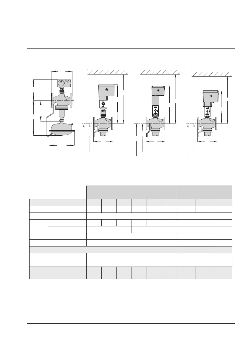
Dimensions and weights∙Type42-36E with Type 2423E Valve balanced by a bellows
Dimensional drawings · Type2423E Valve balanced by a bellows·DN15 to 250
DN15 to 50 DN65 to 100 DN125 to 250
H1
H
H3
H4
L
H
H1
H3
L
H4
H
H1
H3
H4
L
H
H1
Type42-36 E with actuator
Type5827-N1/-N2
Type5827-A1/-A2
4)
Types3374-11/-21 Type3374-25 Type3374-15
Dimensions in mm and
weights
With Types5827-N1/-N2/-A1/-A2 Actuator
With Types3374-11/-21
Actuator
Valve size DN 15 20 25 32 40 50 65 80 100
Length L 130 150 160 180 200 230 290 310 350
Height H1 225 300 355
Height
H2
Forged steel 221 – 243 – 263 269 –
Other materials 223 243 –
Height H3 – 520 540
Height H4 – 820 890
Type42-36E PICV
Height H
2)3)
390 465 520
Diaphragm actuator ØD=225mm, A=160cm²
2)
Weight for PN16
1)
in kg
(approx.)
13.5 14 15 21.5 22 24.5 51 56 71
1)
+10% for cast steel PN 40 and spheroidal graphite iron PN 25
2)
Minimum clearance required to remove the diaphragm actuator: +100mm
3)
Actuator with two diaphragms: Height H +55mm
Fig.3-5: Dimensions of the regulators with a valve balanced by a bellows