ENGLISH-48
Wiring work
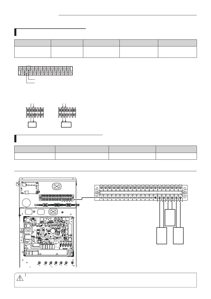
Connection of the back-up boiler
Description No. of wires Mini. / Max. current Thickness Supply Scope
Back-up Boiler 2+ground 10mA / 50mA
0.75mm
2
H05RN-F or
H07RN-F
Field supply (220-240V~,
Input)
L N L N
When it set back up
boiler on the hydro unit
(relay o )
Boiler
B4 : Back-up boiler (L)
B5 : Neutral (N)
Boiler
When it order to back up
boiler operates (relay on)
1. Before the installation, hydro unit should be turned o.
2. Using the appropriate equipment to correct position of terminal
block as shown on the diagram.
3. Make sure EXT-CTRL signal of back up boiler must be 230Vac.
- Do not connect supply power of back up boiler directly.
Heat pump does not work when the Back-up boiler operates.
Connecting for external contact functions
Screw size Tightening torque (N·m) Part Terminal code
M3 0.5~0.75 20P Terminal block 1~20
Connecting external sensors for zone control
1 2 3 4 5 6 7 8 9 10 11 12 13 14 15 16 17 18 19 20
ZONE2
Room
Temp.
(103)
ZONE1
Flow
Temp.
[Tw2_z1]
(103)
ZONE2
Flow
Temp.
[Tw2_z2]
(103)
• When connecting sensors, use a Thermistor with the specications of 10 k at 25
°C
, B constant = 3435 k.
CAUTION
 Loading...