EasyManua.ls Logo

Samsung AM072FXVAFH series User Manual

Samsung AM072FXVAFH series
293 pages
To Next Page IconTo Next Page
Page #1 background imageLoading...
Page #1 background image
AIR CONDITIONER CONTENTS
SYSTEM AIR CONDITIONER
1. Precautions
2. Product Specifications
3. Disassembly and Reassembly
4. Troubleshooting
5. PCB Diagram and Parts List
6. Wiring Diagram
7. Cycle Diagram
8. Key Options
9. Test Operation
10. Reference Sheet
OUTDOOR UNIT
AM072/096/120/144FXVAFH
6
AM072/096/120/144FXVAFR
6
AM072/096/120/144FXVAJH
6
AM072/096/120/144FXVAJR
6
AM072/096/120/192HXWAFR
AM072/096/120/192HXWAJR
AM168/192HXVAFH
6
AM168/192HXVAFR
6
AM168/192HXVAJH
6
AM168/192HXVAJR
6
AM072/096KXVTF
6
AM072/096KXVTJ
6
AM216KXVGJH
AM038/048/055KXWDCH

Table of Contents

Question and Answer IconNeed help?

Do you have a question about the Samsung AM072FXVAFH series and is the answer not in the manual?

Samsung AM072FXVAFH series Specifications

General IconGeneral
BrandSamsung
ModelAM072FXVAFH series
CategoryAir Conditioner
LanguageEnglish

Summary

1. Precautions

1-1 Precautions for the Service

Guidelines for performing service on electrical parts and connections.

1-2 Precautions for the Static Electricity and PL

Handling PCB power terminals and installation place to prevent noise.

1-3 Precautions for the Safety

Safety measures regarding power plugs, wiring, outlets, and grounding.

2. Product Specifications

2-1 The Feature of Product

Details on Dual Smart Inverter System and Dual SSC System Technology.

2-1-2 Changes in comparison to basic mode

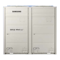
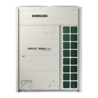
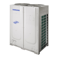
Visual comparison of changes in cabinets and control box/PCB.

2-2 Product Specifications

Detailed specifications for outdoor units, including cooling and heating capacities.

3. Disassembly and Reassembly

3-1 Necessary Tools

Lists essential tools required for disassembly and reassembly procedures.

3-2 Disassembly and Reassembly

Step-by-step procedures for disassembling and reassembling specific outdoor unit models.

4. Troubleshooting

4-1 Check-up Window Description

Explains the functions of various display elements and buttons on the check-up window.

4-2 PCB Description

Identifies and describes the functions of numbered components on the PCB.

4-3 Service Operation

Details special operations and key inputs for outdoor unit service.

4-4 Appropriate Measures for Different Symptom

Provides troubleshooting flowcharts for various outdoor unit symptoms.

5. PCB Diagram and Parts List

5-1 ASS'Y PCB MAIN

Illustrates the main assembly PCB with numbered components and their functions.

6. Wiring Diagram

6-1 AM072/096/120/144FXVA

Wiring diagram for specific outdoor unit models AM072 to AM144 FXVA.

7. Cycle Diagram

7-1 AM072FXVAFH/AM072FXVAJH

Refrigerant cycle diagram for specific AM072FXVAFH/JAH models.

8. Key Options

8-1 Outdoor unit option switch settings

Explains the function and settings of outdoor unit option switches like SW51 to SW57.

9. Test Operation

9-1 Auto Trial Operation

Details the process and inspection items for Auto Trial Operation.

10. Reference Sheet

10-1 Nomenclature

Explains the model naming convention and its components.

Related product manuals