Samsung Electronics
12-3 PCB Inspection Method
12-3-1 Pre-inspection Notices
1. Check if you pulled out the AC power plug when you eliminate the PCB or front panel.
2. Don’t hold the PCB side not impose excessive force on it to eliminate the PCB.
3. Don’t pull the lead wire but hold the whole housing to connect or disconnect a connector to the PCB.
4. In case of outdoor PCB disassembly, check first the complete discharge of condenser (C103) after 30 seconds power off.
12-3-2 Inspection Procedure
1. Check connector connection and peeling of PCB or bronze coating pattern when you think the PCB is broken.
2. The PCB is composed of the 3 parts.
1. Indoor Main PCB Part : MICOM and surrounding circuit, relay, room fan motor driving circuit and control circuit, sensor driving
circuit, power circuit of DC12V and DC5V, and buzzer driving circuit.
1. Display part : LED lamp, Switch, Remocon module
1. Outdoor Main PCB part : MICOM and surrounding circuit. IPM and PFC circuit and control circuit.
1. EMI PCB Part : Line filter and Noise Capacitor, Varistor
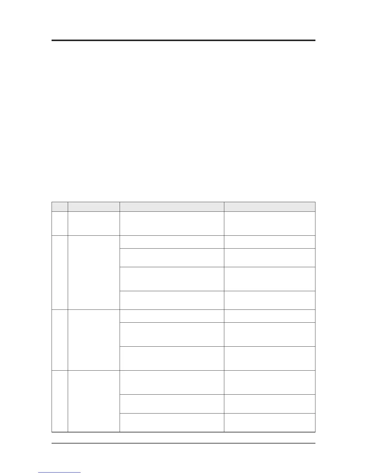
12-3-3 Indoor Detailed Inspection Procedure
No Procedure Inspection Method Cause
1 Plug out and pull the PCB
out of the electronic box.
Check the PCB fuse.
1) Is the fuse disconnected?
• Over current
• Indoor Fan Motor Short
• AC Part Pattern Short of the MAIN PCB
2 Supply power.
If the operating lamp
twinkles at this time,
the above 1)~3) have
no relation.
Checking the power voltage.
1) Is the DB71 input voltage AC200V~AC240V?
• Power Cord is fault, Fuse open. Wrong Power
Cable Wiring, AC Part is faulty.
2) Is the voltage between both terminals of the
C104 on the 2
nd
side of the transformer DC12V
±0.5V?
• Switching Trans or Power Circuit is faulty
3) Is the voltage between both terminals of OUT
and GND of IC19(KA78L05) DC5V ±0.5V?
• Power Circuit is faulty, Load Short
3 Press the ON/OFF button.
Checking the power voltage.
1) Is the voltage over AC180V being imposed on
1) terminal #3 and #5 of the fan motor
connector(CN72)?
• Relay(RY71) Coil Disconnection, IC05 is faulty
2) Check the voltage of both terminals of
terminal block 1 and N(1) after 3 minute
operation.: AC220V
• Relay(RY71) Contact is faulty
4 Press the ON/OFF button.
1. FAN Speed [High]
2. Continuous Operation
1) Is the voltage over AC180V being imposed on
1) terminal #3 and #5 of the fan motor
connector(CN72)?
• Fan Motor of the indoor is faulty
2) The fan motor of the indoor unit doesn’t run.
• Fan Motor Connector(CN72) is faulty
3) The power voltage between terminal #3 and #5
of the connector(CN72) is 0V.
• ASS’Y Main PCB is faulty
• Connection is faulty
12-20
 Loading...