Samsung Electronics
14-7 Installation Diagram of Indoor Unit and Outdoor Unit
14-7-1 Air-Purge Procedure
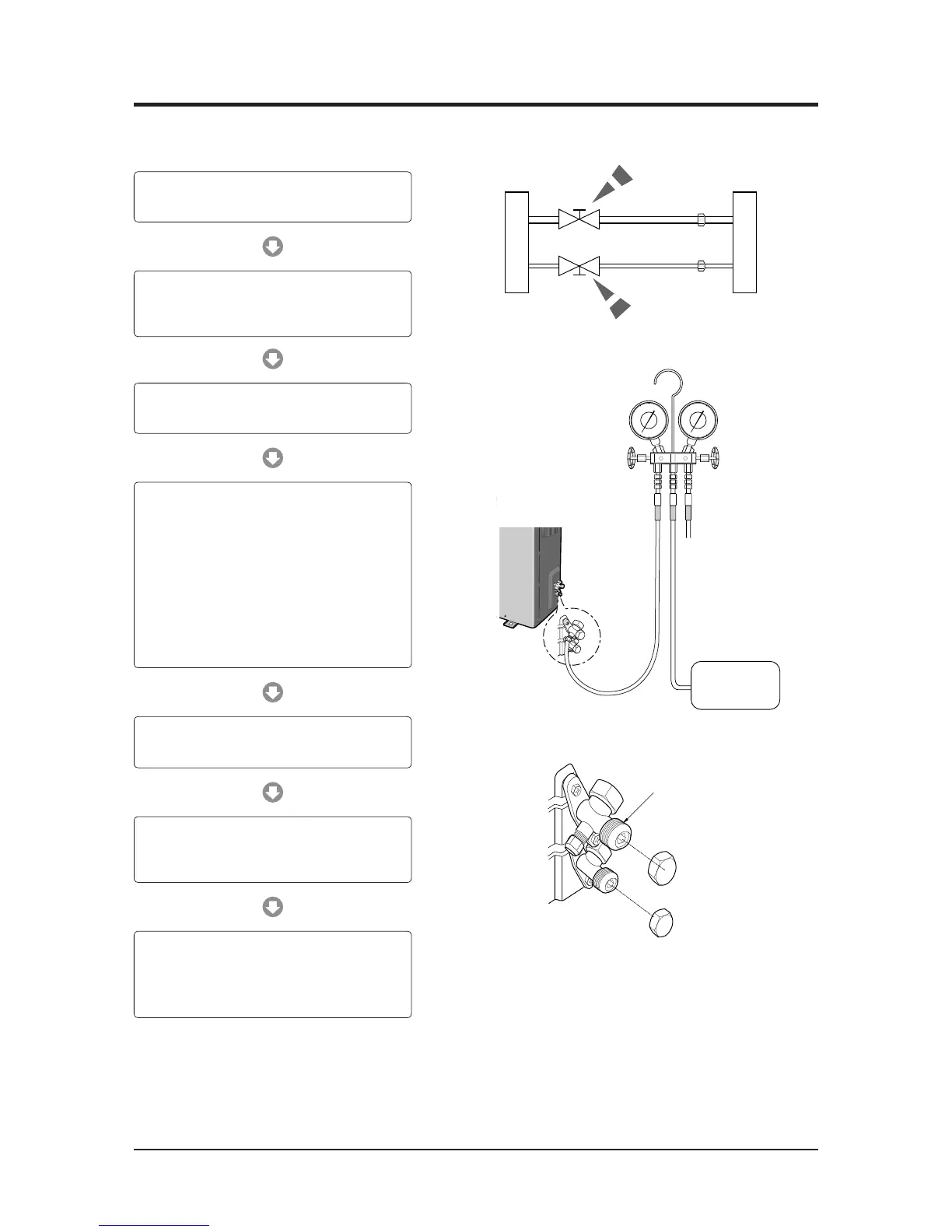
1) Connect each assembly pipe to the appropriate valve
on the outdoor unit and tighten the flare nut.
3) Open the valve of the low pressure side of
manifold gauge counter-clockwise.
4) Purge the air from the system using vacuum pump
for about 30 minutes.
– Make sure that pressure gauge show
-0.1MPa(-76cmHg) after about 30 minutes.
– This procedure is very important in order to avoid
gas leak.
– Turn off the vacuum pump.
– Close the valve of the low pressure side of
manifold gauge clockwise.
– Remove the hose of the low pressure side
of manifold gauge.
7) Check for gas leakage.
- At this time, especially check for gas leakage from
the 3 way valve’s stem nuts, and from the service
port cap.
2) Connect the charging hose of low pressure side of
manifold gauge to the packed valve having a service
port as shown at the figure.
5) Set valve cork of both liquid side and gas side of
packed valve to the open position.
6) Mount the valve stem nuts and the service port cap
to the valve, and tighten them at the torque of
183kgf•cm with a torque wrench.
 Loading...