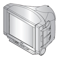
PCB Diagram
9-2 Samsung Electronics
9-1-3 Main Board Connector Pin
CN503
Connected to the Main Ass'y
CN901
Connected to the Control Ass'y
PIN No. Pin Name
1 STD-LED
2 TIME-LED
3 GND
4 VCC
CN501A
Connected to the CRT Ass'y
PIN No. Pin Name
1 B-OUT
2 G-OUT
3 R-OUT
4 GND
5 SENSE
6 GND
7 N.C
8 GND
9 GND
10 N.C
11 GND
12 HEATER
13 N.C
14 B+200V
PIN No. Pin Name
1 GND
2 N.C
3 GND
4 HEATER
5 N.C
6 B+200V
CN502
Connected to the CRT Ass'y
PIN No. Pin Name
1 B-OUT
2 G-OUT
3 R-OUT
4 GND
5 SENSE
6 GND
7 N.C
8 GND
CN900
Connected to Micom Jig
PIN No. Pin Name
1 SCL
2 GND
3 B+3.3V
4 SDA
CN902
Connected to the Control Ass'y
PIN No. Pin Name
1 KEY-IN2
2 KEY-IN1
3 GND
4 KEY-IN3
PIN No. Pin Name
1 AV2-R-IN
2 AV2-L-IN
3 AV2-L-OUT
4 AV2-R-OUT
5 GND
6 AV2-V-IN
7 GND
8 AV2-V-OUT
CN701
Connected to the AV Ass'y
 Loading...
