11
ENGLISH
Working on power supply
Connecting power/communication cable
f Turn the power o before working on the power supply.
f Maximum cable length and the amount of voltage drop for AHU KIT power/communication cables should be within
10%.
f When installing the MCCB/ELB or ELCB, consider Power Rating of the AHU motor for correct capacity.
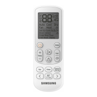
f Connect F3, F4 of AHU KIT terminal to Wired Remote Control.
f Use the appropriate tools for wiring and make sure the wiring is connected tightly within
the tightening torque to withstand the external pressure. Arrange the wires so that cover or
other parts does not get loose. Otherwise, it may cause overheating, electric shock or re.
Tightening torque (kgf•cm)
M4 12.0~14.7
f To protect the product from external shock or water, put the power and communication cable into a power cable
protection box.
f Connect the power cable through MCCB/ELB or ELCB.
f Maintain more than 50mm distance between the power cable and communication cable.
• The circuit diagram for wiring represents only an outline so the detailed information about actual installation
work is not described.
• In principle, AHU KIT power supply should be provided separately from an outdoor unit.
• Do not distribute the communication cable as communication error may occur.
• Do not distribute the power cable of terminal block for 2 AHU KITs from 1 AHU KIT.
• When peeling the sheath of power cable, use the appropriate tools to prevent damage inside the wire.
• Make sure that more than 20mm of power and communication cable of AHU KIT is inside the electric parts.
• Communication cable should be installed separately from power cable or other communication cables.
CAUTION
Selecting a solderless terminal
1. Select a solderless terminal on the basis of nominal sectional area for a connecting power cable.
2. Insulate the solderless terminal and connection part of the connecting power cable with sheath.
Nominal sectional area for cables
(mm
2
)
1.5 2.5 4
Silver soldering
Nominal diameter for screws (mm) 4444 4
B
Standard dimension (mm) 6.6 8 6.6 8.5 9.5
Allowance (mm) ±0.2 ±0.2 ±0.2
D
Standard dimension (mm) 3.4 4.2 5.6
Allowance (mm)
+0.3
-0.2
+0.3
-0.2
+0.3
-0.2
d1
Standard dimension (mm) 1.7 2.3 3.4
Allowance (mm) ±0.2 ±0.2 ±0.2
E Min. 4.1 6 6
F Min. 665
L Max. 16 17.5 20
d2
Standard dimension (mm) 4.3 4.3 4.3
Allowance (mm)
+0.2
0
+0.2
0
+0.2
0
t Min. 0.7 0.8 0.9
 Loading...