12
Installing an AHU KIT
Specication of electronic wire
Power supply MCCB ELB Power cable Earth cable Communication cable
Max : 242V
Min : 198V
XA
XA, 30 mmA
0.1 s
2.5 mm
2
2.5 mm
2
0.75~1.5 mm
2
f Decide the capacity of ELB and MCCB by below formula.
The capacity of ELB, MCCB X [A] = 1.25 X 1.1 X ∑Ai
❋ X : The capacity of ELB, MCCB
❋ ∑Ai : Sum of Rating currents of each indoor unit.
❋ Refer to each installation manual about the rating current of indoor unit.
❋ Rating current
Unit Model Rating current
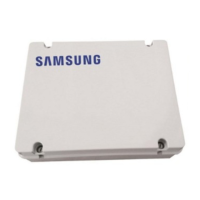
AHU KIT MCM-D201N 0.5A
Connection diagram of ASS'Y Control
Installation example 1) Connection diagram of 1 outdoor unit + 1 AHU
1(L) 2(N)
F1 F2 F3 F4 V1 V2 1 243CBA
mA
-+ Vd Vd
MCCB/ELB or
ELCB
220~240V
Supply
power
Sensor
(mA)
Sensor
(PT1000)
Defrost signal
Contact signal for AHU
fan ON
F4: Wired remote controller communication cable
F3: Wired remote controller communication cable
F2: Outdoor unit communication cable
F1: Outdoor unit communication cable
Input contact signal for fan operation
status and o power.
Wired remote controller Outdoor Unit

 Loading...


