8
Installing an AHU KIT
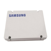
Installing ASS'Y Control
1. Check the installation location of ASS'Y Control.
f You can choose either AHU attachment type or AHU separation type depending on the installation environment.
2. Check the length of connection cable of ASS'Y Control.
f The length of provided connection cable is 7m.
3. Make sure the location has waterproof and re prevention structure.
f Make sure that the ASS'Y Control is not exposed to sunlight by covering with a case which has waterproof and re
prevention structure.
Terminal Block
Main PBA
Functions of ASS'Y Control
f When using the ASS’Y Control alone, you can use EEV of 10~40 HP Capacity.
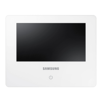
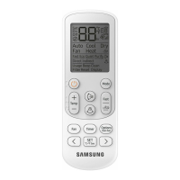
f ASS'Y Control adjusts rate of ow for EEV refrigerant and performs control functions through communication with an
indoor unit or wired remote controller.
f The contact signal for AHU fan operation is sent from ASS'Y Control. When AHU is in Cool/Heat/Fan mode, terminal block
No.1 and No.2 will output contact signal to turn the fan on. At this time, the output is contact signal and not be used for
power supply of motor. (Refer to p.12~13)
f The terminal block No.3 and No.4 will receive the signal for fan operation status and the signal is the input signal which
AHU KIT control part receives. At this time, the input signal sholud be input as only OPEN/SHORT signal not the signal that
has separate voltage level. (Refer to p.10)
- When the fan operates normally: The terminal block No.3 and No.4 are SHORT status.
- When the fan does not operate: The terminal block No.3 and No.4 are OPEN status.
- Set SEG 21 of installation option 05 series to ‘1(Use)’ to use fan feedback for system protection. (Refer to p. 26)
f The terminal block Vd/Vd is output defrost signal. (There exist some time delay.)
- When installing a defrost bypass valve, set SEG22 of 05 series installation option as “1”.
f Connect 220~240V to the terminal block 1(L)/2(N).
f The terminal block of communication cable (F1, F2) is connected with communication of Outdoor Unit. When installing
additional AHU KIT, the communication (F1, F2) should be connected with the communication (F1,F2) of AHU KIT which
is additionally installed. (Refer to p.12~13)
f The communication cable(F3, F4) is the communication group of wired remote controller. (Refer to p.12~13)
f When installing 10 HP of ASS'Y Control, you shouldn't perform additional control of ASS'Y Control.

 Loading...


