EasyManua.ls Logo

Samsung RT53 - Page 46

Samsung RT53
70 pages
To Next Page IconTo Next Page
To Previous Page IconTo Previous Page
Loading...
Total Ver.02
Uploaded by
epalarcon9
ninguno
Full description
Save
Embed
Print
RELATED TITLES
304 views
Share
Hotpoint,Mba
4033 Cv
LG_MULTI_F_3828A20097W_1[1]
Samsung
Refrigerador
346481235-
WD856UHSAWQ-
TROUBLESHOOTING
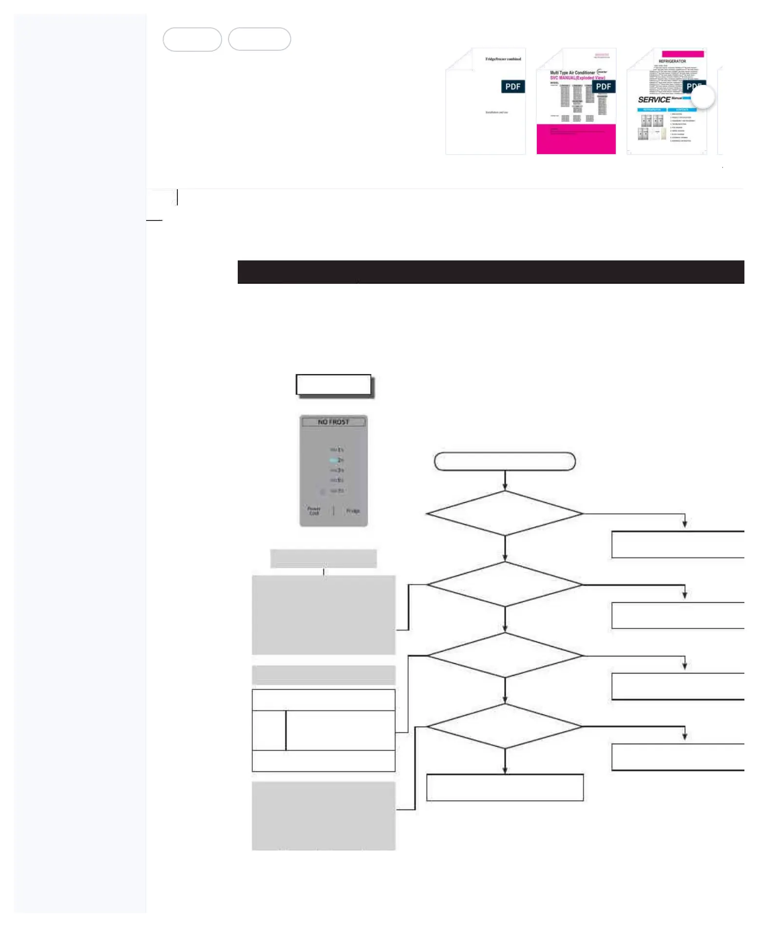
2) When the EXT-Sensor is defective
MAIN PCB Connector
CN31 is inserted properly?
EXT Sensor is
normal?
Voltage between
MAIN PCB Connector CN31-"1"(YEL)
and CN31-"2"(YEL)?
Input Voltage at IC10
MICOM Pin #21 is normal?
Start
PCB and Temp Sensor are normal.
Check the connector contact.
Connector contact defect / Reconnect
Replace Temp Sensor
Check the wire connection
Check Soldering Defect & Short
No
No
No
NO
(V
al
ue < 0
.6
V or V
al
ue > 4
.6
V)
No
Y
es
Y
es
Y
es
Y
es
Sensor MICOM/Connector #
EXT
Between Connector CN31-
"1"(YEL) and CN31-
"2"(YEL)
Voltage : Between 4.6V ~ 0.6V
** Sensor Resistance Reading Location **
EXT : Between CN31 #1 and #2.
** Located in the PCB Box
** 0Ω : Short /
∞Ω : Open
Voltage at IC10 MICOM #21
is the same as the value
between CN31-"1"(YEL) and
CN31-"2"(YEL) of the CN31
on MAIN PBA.
Refer to Circuit Diagram
DAT
A1.
T
emp
T
able
ERROR CODE

Related product manuals