Alignment and adjustment
5-22 Samsung Electronics
1. PLL
1) VCR ÒPBÓ, Color bar (SP).
2) RPD and EVR.
3) Connect oscilloscope probe to RPD.
4) Press the ÒBLC (MODE UP/DOWN)Ó button so
that the OSD state is Ò08 PLL EPR:XX EVR:XXÓ.
5) Adjust the ÒD.ZOOM+/- (DATA UP/DOWN)Ó
button so that RPD level is DC1.8 ± 0.1Vp-p.
6) Be sure to press the ÒDISPLAY(CONFIRM)Ó
button to memorize setting.
7) The OSD shows ÒCONFIRM !Ó.
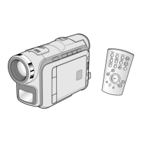
2. Brightness
1) VCR ÒPBÓ, Color bar (SP).
2) G-OUT and EVR.
3) Connect an oscilloscope probe to G-OUT.
4) Press the ÒBLC (MODE UP/DOWN)Ó button so
that the OSD state is Ò02 BRIGHT EPR:XX
EVR:XXÓ.
5) Adjust the ÒD.ZOOM+/- (DATA UP/DOWN)Ó
button so that bright(Green) level is 8.0Vp-p.
6) Be sure to press the ÒDISPLAY(CONFIRM)Ó
button to memorize setting.
7) The OSD shows ÒCONFIRM !Ó.
5-2-4 (b) ADJUSTMENT
Note : 1. From this point forward, the structure of every adjustment is as follows.
2. See page 5-24 for the location of test points and adjustments.
Test point
Step Adjustment Item
1. Mode and input signal/
alignment tape
2. Test point and ADJ. part
3. Result and Remarks
ADJ. point
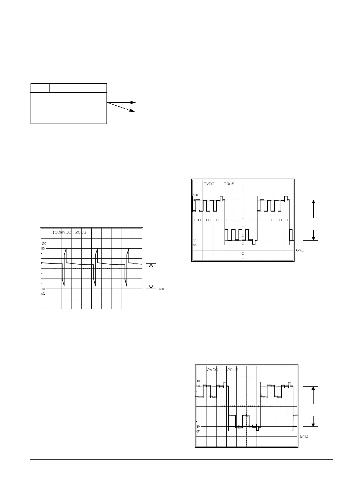
3. R-Sub Brighness
1) VCR ÒPBÓ, Color bar (SP).
2) R-OUT and EVR.
3) Connect an oscilloscope probe to R-OUT.
4) Press the ÒBLC (MODE UP/DOWN)Ó button so
that the OSD state is Ò04 R SUB EPR:XX
EVR:XXÓ.
5) Adjust the ÒD.ZOOM+/- (DATA UP/DOWN)Ó
button so that R-OUT(Red) level is 8.0Vp-p.
6) Be sure to press the ÒDISPLAY(CONFIRM)Ó
button to memorize setting.
7) The OSD shows ÒCONFIRM !Ó.
 Loading...