Alignment and adjustment
Samsung Electronics 5-19
5-2-3 EVF Adjustment
Note : From this point forward, the structure of every adjustment is as follows.
Test point
Step Adjustment Item
1. Mode and input signal/
alignment tape
2. Test point and ADJ. part
3. Result and Remarks
ADJ. point
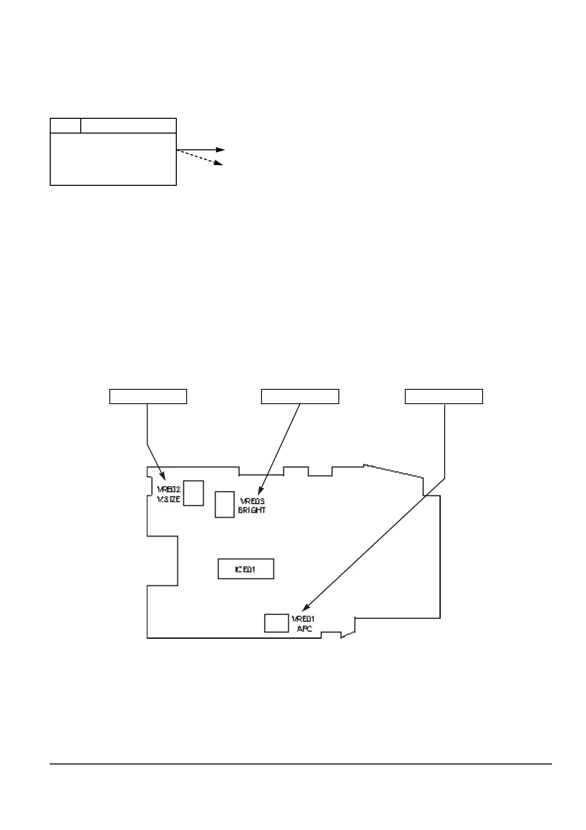
2. V. Size
1) VCR ÒPBÓ, Alignment tape (Lion pattern).
2) Viewfinder and VRE02.
3) Adjust VRE02 so that the counter circle on the
lion pattern is perfect by round.
3. Bright
1) VCR ÒPBÓ, Alignment tape (Lion pattern).
2) Viewfinder and VRE03.
3) Adjust the VRE03 so that the 3rd and 4th steps of
the lion pattern can be distinguished.
1. AFC
1) VCR ÒPBÓ, Alignment tape (Lion pattern).
2) TP1 and VRE01.
3) Connect digital voltmeter probe to TP1.
4) Adjust VRE01 so that the voltage is
DC 2.5V ± 0.1V.
EVF PCB (Component side)
1. AFC2. V. Size 3. Bright
 Loading...