Switch Control Conguration
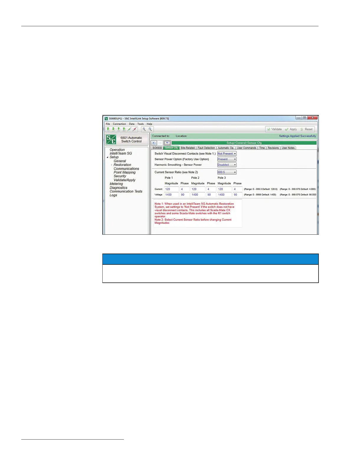
Click on the Sensor Cong tab. See Figure 8. This screen congures sensor calibration
data for Scada-Mate Switching Systems, and PME, PMH, or Vista Underground
Distribution Switchgear sensors. The switch control uses this data to calibrate sensor
input to the voltage and current amplitude accuracy specied for S&C Sensors. The 6802
and 6803 controls are supplied with a yellow sheet showing the current and voltage ratio
information (also stamped on each sensor). Enter the information on this screen.
The 6801 controls do not have this card, but the information is part of the data package
provided with the Scada-Mate switch. Because the controls and switches are typically
shipped separately it is important to make sure the information stays with the switch
until it is pared with a control.
Sensor Configuration
Figure 8. The Setup>General>Sensor Configuration screen (6801 switch control shown).
NOTICE
Ratios must be entered for phase B when phases A, B, and C are measured. The
phase B ratios are used to adjust all voltage scales for 15-, 25-, or 35-kV systems.
12 S&C Instruction Sheet 1045-511

 Loading...
