20 S&C Instruction Sheet 761-515
Installation
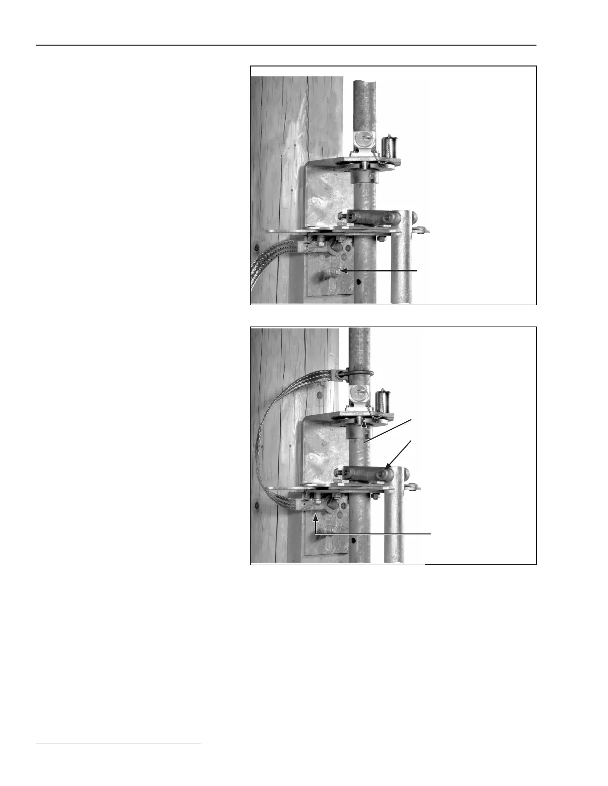
Step 19
Bolt the foot-bearing assembly to the pole at
the position shown on the erection drawing.
Use one of the mounting bolts to attach one
end of the grounding strap (the end with the
grounding connector attached) to the foot-
bearing assembly. See Figure 18. The grounding
recommendations within this document may
differ from the standard operating and safety
procedures of certain electric utility companies.
Where a discrepancy exists, the operating
procedures of the electric utility apply.
Foot-bearing assembly
Figure 18. Attach the foot-bearing assembly.
Step 20
Fasten the operating-handle assembly to the
lowest vertical operating-pipe section using the
piercing set screws furnished. Figure 19.
Tighten the piercing set screws on the oper-
ating handle assembly, piercing the pipe, and
continue turning until a firm resistance is felt.
Attach the interlock bracket to the foot-
bearing assembly, using the ½–13 × 1½-inch
cap screws, spacers, and ½-inch lock washers
furnished.
With the switch in the Closed position, use
the interlock bolt to position the locking disc
so the bolt enters the closed-position slot in the
disc (and will enter the open-position slot when
the switch is in the Open position).
Interlock bolt positioned
in closed-position slot
Operating-handle
assembly
1/2–13 11/2-inch cap
screws, spacers,
and lockwashers
Figure 19. Fasten the operating-handle assembly.
 Loading...


