S&C Instruction Sheet 761-515 21
Installation
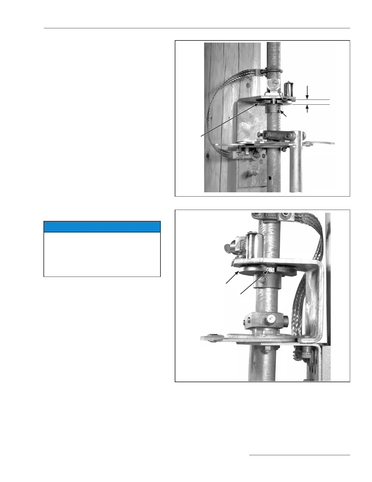
Step 21
Hold the locking disc 3/8-inch below the interlock
bracket, and drill 7/16-inch diameter holes
through the vertical operating pipe section,
using the holes in the locking disc collar as a
guide. Attach the locking disc to the pipe using
the 3/8–16 × 3-inch cap screw, lockwasher, and
nut furnished. See Figure 20.
⅜–16 3-inch cap
screw, lockwasher,
and nut
Locking
disc
⅜-inch
Figure 20. Attach the locking disc.
Step 22
NOTICE
Key interlocks are intended for proper
sequencing of switch operations; they
are not intended to provide security. The
operating handle assembly includes a
swing-away hasp for padlocking the switch
in either the Open or Closed position.
Block one of the two slots in the locking disc
with the blocking screw provided. (The slot to
be blocked depends on whether a locked-open
or locked-closed arrangement is required.) See
Figure 21.
Blocking screw
Locking disk
Figure 21. Blocking slot in the interlock disc.
 Loading...


