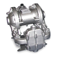
s20mdl1sm-REV0708 Model S20 Metallic Page 24
Check Valve Drawing
CHECK VALVE SERVICING
Before servicing the check valve
components, fi rst shut off the suction
line and then the discharge line to the
pump. Next, shut off the compressed
air supply, bleed air pressure from the
pump, and disconnect the air supply
line from the pump. Drain any remaining
fl uid from the pump. The pump can now
be removed for service.
To access the check valve
components, remove the manifold
(item 23 or item 24 not shown). Use a
9/16" wrench or socket to remove
the fasteners. Once the manifold is
removed, the check valve components
can be seen.
Inspect the check balls (items 2) for
wear, abrasion, or cuts on the spherical
surface. The check valve seats (item
36) should be inspected for cuts,
abrasive wear, or embedded material
on the surfaces of both the external
and internal chambers. The spherical
surface of the check balls must seat
fl ush to the surface of the check valve
seats for the pump to operate to
peak effi ciency. Replace any worn or
damaged parts as necessary.
Re-assemble the check valve
components. The seat should fi t into the
counter bore of the outer chamber.
The pump can now be reassembled,
reconnected and returned to
operation.
METALLIC SEATS
Two o-rings (or conductive PTFE
seals) (item 40) are required for metallic
seats.
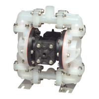
with Non-Metallic
Seats
with Metallic Seats

 Loading...