s20mdl1sm-REV0708 Model S20 Metallic Page 14
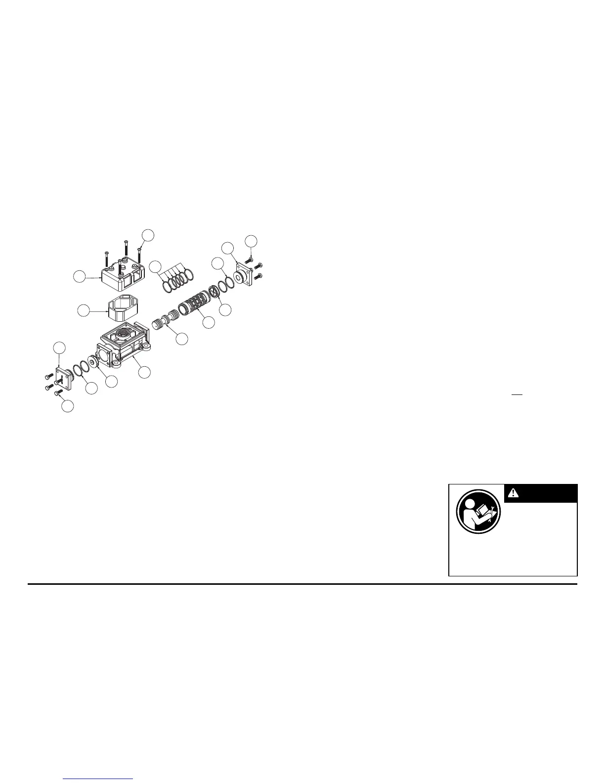
Air Valve Servicing, Assembly Drawing & Parts List
(Use With Aluminum Centers Only)
1-H
1-G
1-E
1-F
1-D
1-C
1-A
1-B
1-B
1-C
1-F
1-E
1-D
1-D
1-J
**Note: Pumps equipped with this valve assembly are not ATEX compliant
AIR VALVE ASSEMBLY PARTS LIST
Item Part Number Description Qty
1 031-173-000 Air Valve Assembly 1
1-A 095-109-157 Body, Air Valve 1
1-B 031-139-000 Sleeve and Spool Set 1
1-C 132-029-357 Bumper 2
1-D 560-020-360 O-Ring 10
1-E 165-127-157 Cap, End 2
1-F 170-032-330 Hex Head Capscrew 1/4-20 x .75 8
1-G 530-028-550 Muffl er 1
1-H 165-096-551 Muffl er Cap 1
1-J 706-026-330 Machine Screw 4
**AIR VALVE ASSEMBLY PARTS LIST
1 031-173-001 Air Valve Assembly 1
Consists of all components above except:
1-F 170-032-115 Hex Head Capscrew 1/4-20 x .75 8
1-J 706-026-115 Machine Screw 4
AIR DISTRIBUTION VALVE SERVICING
To service the air valve fi rst shut off the
compressed air, bleed pressure from the
pump, and disconnect the air supply line
from the pump.
Step #1: See COMPOSITE REPAIR PARTS
DRAWING.
Using a 9/16" wrench or socket, remove
the four hex capscrews (items 12). Remove
the air valve assembly from the pump.
Remove and inspect gasket (item 19)
for cracks or damage. Replace gasket if
needed.
Step #2: Disassembly of the air valve.
Using a 7/16" wrench or socket, remove
the eight hex capscrews (items 1-F) that
fasten the end caps to the valve body.
Next remove the two end caps (items 1-E).
Inspect the two o-rings (items 1-D) on each
end cap for damage or wear. Replace the
bumpers as needed.
Remove the bumpers (items 1-C).
Inspect the bumpers for damage or wear.
Replace the bumpers as needed.
Remove the spool (part of item 1-B)
from the sleeve. Be careful not to scratch
or damage the outer diameter of the spool.
Wipe spool with a soft cloth and inspect for
scratches or wear.
Inspect the inner diameter of the sleeve
(part of item 1-B) for dirt, scratches, or other
contaminants. Remove the sleeve if needed
and replace with a new sleeve and spool
set (item 1-B).
Step #3: Reassembly of the air valve.
Install one bumper (item 1-C) and one
end cap (item 1-E), with two o-rings (items
1-D), and fasten with four hex capscrews
(items 1-F) to the valve body (item 1-A).
Remove the new sleeve an spool set
(item 1-B) from the plastic bag. Carefully
remove the spool from the sleeve. Install the
six o-rings (item 1-D) into the six grooves
on the sleeve. Apply a light coating of
grease to the o-rings before installing the
sleeve into the valve body (item 1-A), align
the slots in the sleeve with the slots in the
valve body. Insert the spool into the sleeve.
Be careful not to scratch or damage the
spool during installation. Carefully insert
the sleeve into the bumper and end cap
(with o-rings) and fasten with the remaining
hex capscrews.
Fasten the air valve assembly (item
1) and gasket to the pump. Connect the
compressed air line to the pump. The pump
is now ready for operation.
Read these instructions
completely, before
installation and start-up.
It is the responsibility of
the purchaser to retain
this manual for reference. Failure to
comply with the recommendations stated
in this manual will damage the pump, and
void factory warranty.
IMPORTANT
 Loading...