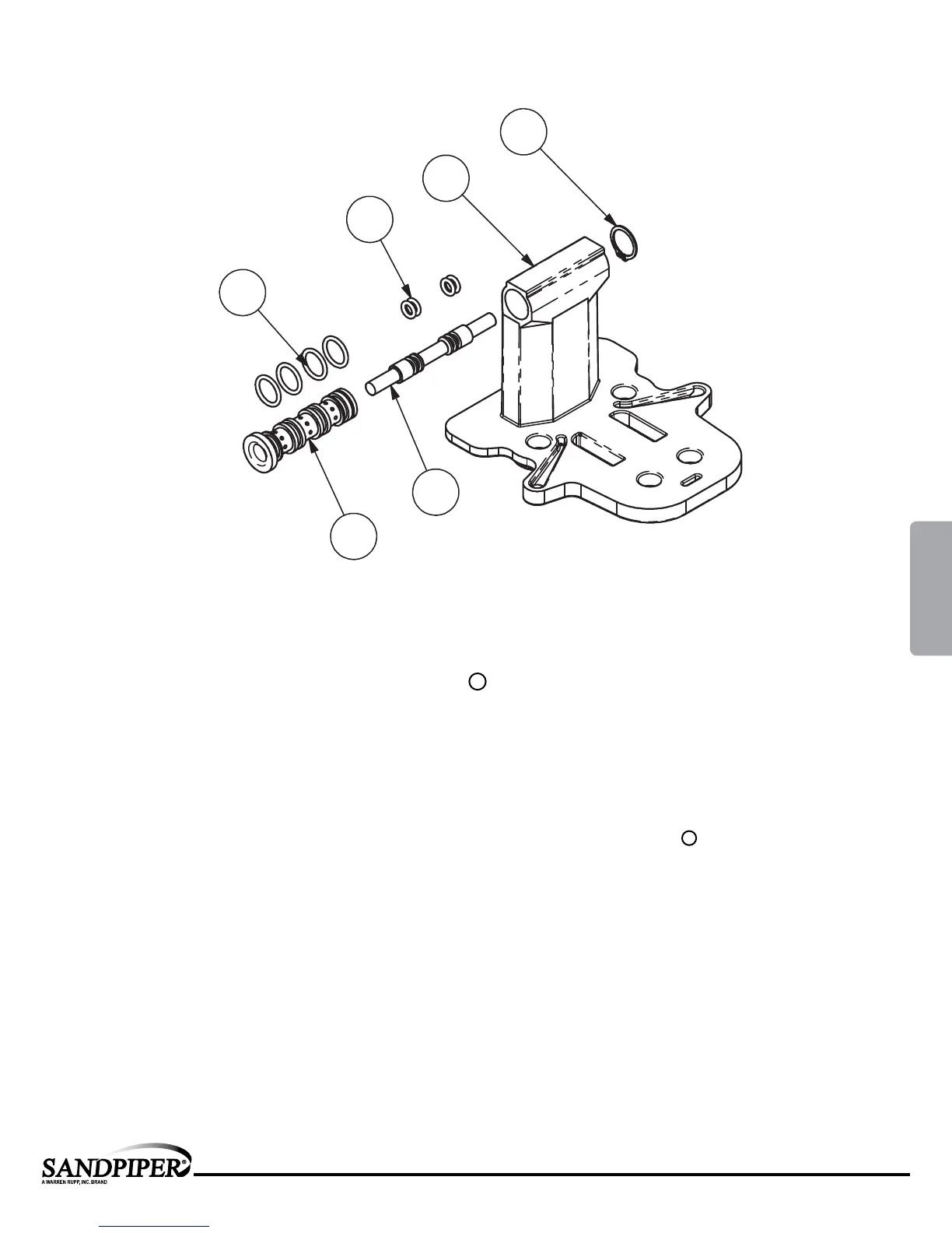
Pilot Valve Assembly
PILOT VALVE ASSEMBLY PARTS LIST
Item Part Number Description Qty
4 095.074.001 Pilot Valve Assembly 1
4A 095.071.557 Pilot Valve Body 1
4B 755.025.162 Pilot Valve sleeve 1
4C 560.033.360 O-Ring 4
4D 775.014.115 Pilot Valve Spool 1
4E 560.023.360 O-Ring 4
4F 675.037.080 Retaining Ring 1
Pilot Valve Servicing
With Pilot Valve removed from pump.
Step 1: Remove snap ring (4F).
Step 2: Remove sleeve (4B), inspect O-Rings (4C),
replace if required.
Step 3: Remove spool (4D) from sleeve (4B),
inspect O-Rings (4E), replace if required.
Step 4: Lightly lubricate O-Rings (4C) and (4E).
Reassemble in reverse order.
4F
4A
4D
4B
4C
4E
LEGEND:
= Items contained within Air End Kits
st1dl5sm-rev0717
www.sa n dpiper p ump.co m
Model ST1/ST25 • 12
MODEL SPECIFIC
4: AIR END