TPMS1209C01 User Manual
Page 5 of 23
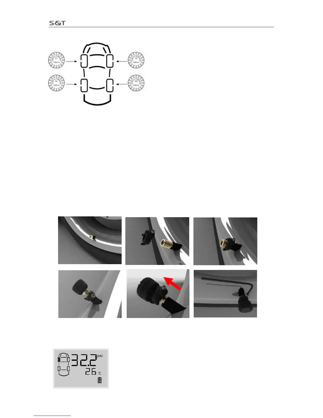
Note: The transmitters must be installed onto corresponding tire position as marked on the top.
Note: FL: stands for front left tire
FR: stands for front rear tire
RL: stands for rear left tire
RR: stands for rear right tire
If the vehicle equipped with spare tire or trailer tires, please refer to
“
VIII. Add New Transmitter or Replace Transmitter”.
Transmitter Installation steps:
1. Turn on the monitor and ensure it works normally.
2. Remove the current tire valve cap.
3. Put the security lock on the valve, ensure the side with screw to the direction which easy for operating.
4. Install the transmitter onto the valve. Ensure the transmitter being installed onto the corresponding tire
according to transmitter’s marks.
5. Connect the meshing parts of the Lock and the Transmitter to make them an integrated part.
6. Screw the transmitter and security lock firmly with the wrench.
7. After transmitters are installed, they will start working and sending signals to the monitor. As showed
below, the front left tire was installed with a transmitter and the monitor has received the information sent
by it.