2.1 National Wiring rules may contain restrictions concerning the installation of these
units in bathrooms.
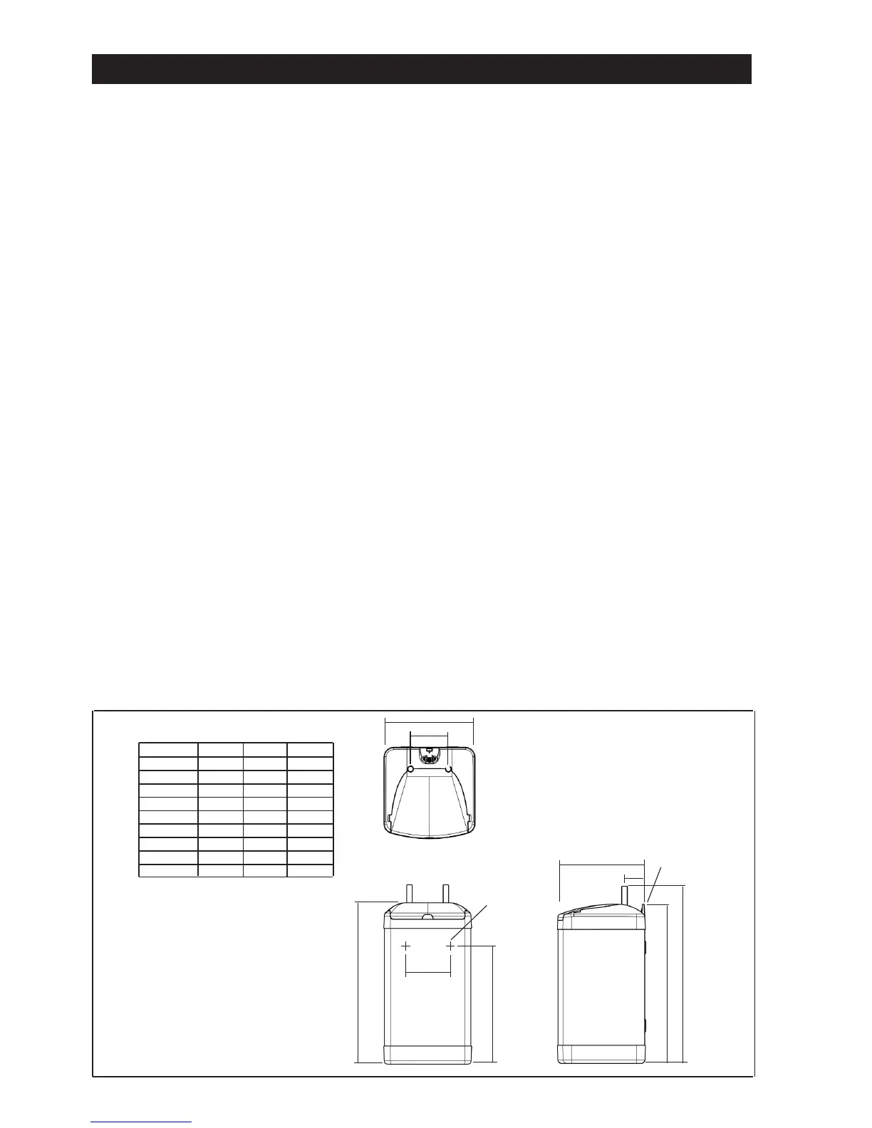
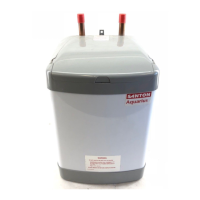
2.2 The unit should be vertically wall mounted using the screws and plugs provided.
Position the bottom two screws as shown in Figure 5 with heads 3mm from the
wall. Hang the Heater and secure with the top screw.
Alternatively it can be oor mounted on it’s base. The water connections must
always be to the top of the unit.
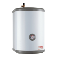
2.3 Enough space should be left at the top above the unit for pipe connections and
access to the Temperature/Pressure Relief Valve (if tted). Refer to Figure 5 and
the Dimensions Table to determine a suitable position for the heater.
2.4 NOTE: Ensure that the wall can support the full weight of the unit
(see TECHNICAL SPECIFICATIONS) and that there are no hidden services
(electricity, gas, or water) below the surface of the wall.
2.5 DO NOT install where the unit may freeze.
2.6 Refer to the section IMPORTANT INSTALLATION POINTS to determine which
valves and accessories are required. Plumb in the valves in the sequence shown in
the relevant Diagrams ( Figures 1, 2, and 3).
2.7 Both inlet and outlet pipes are clearly labeled. The pipes are 15mm copper tube
and are suitable for compression ttings.
It is recommended that a WRAS listed isolating valve (not supplied) is tted on
the cold water supply to the heater. Several hot outlets can be served.
2.8 Do not use solder joints as this will damage the heater and may prevent servicing
under warranty.
2.9 Plumbers Paste must not be used as it can impair the operation of the valves.
5