L
1
N
2
3
HTG
ON
DHW
ON
L
N
2
3
1
L
2
N
3
4
5 6 7 8 9 10
1
2 3
4
5 6 7 8 9 10
(Supply)
1
2 3
G
W
Bl
2
0 GY
3
G
1
Br Bl
2
0
L
N
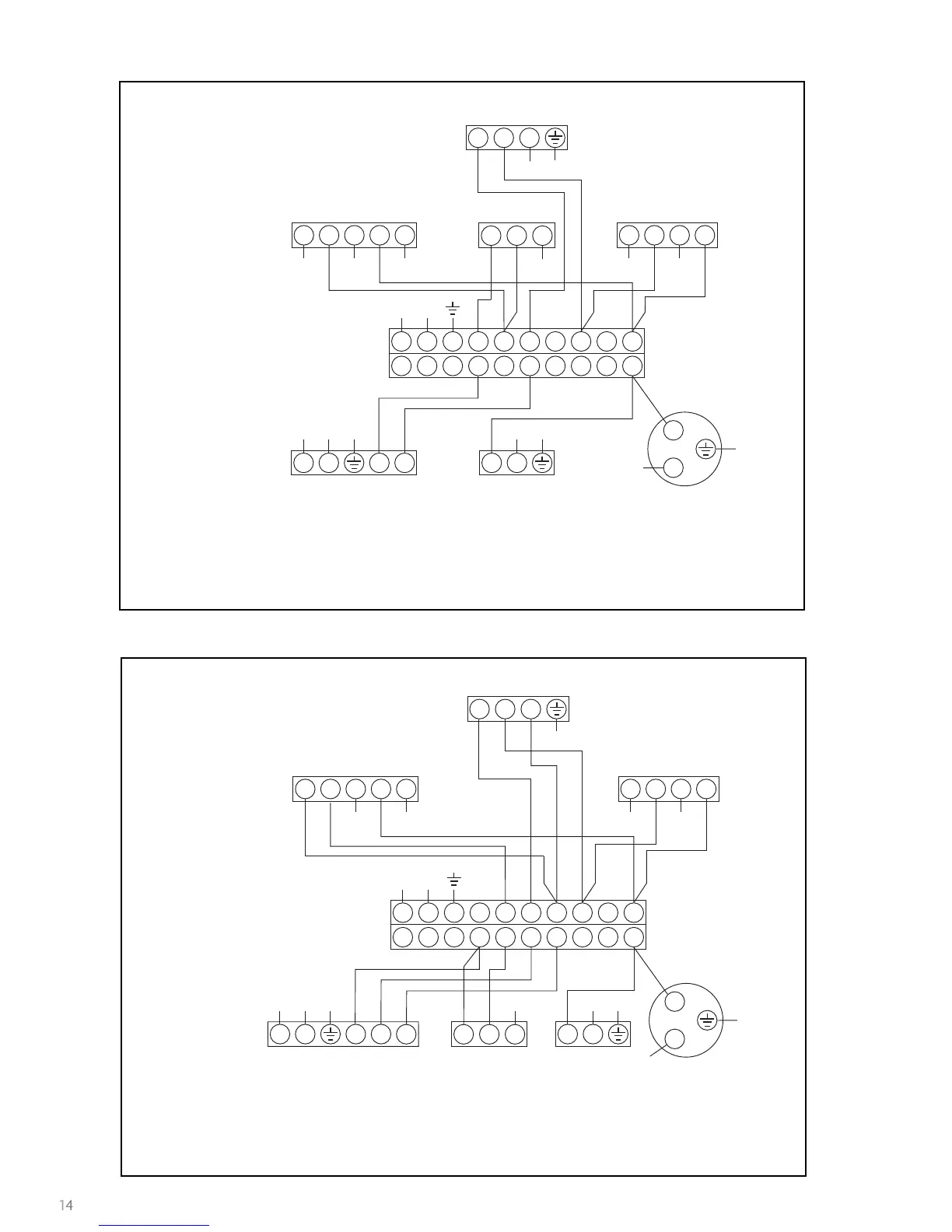
Programmer Boiler Pump
Zone valve (HTG)
Premier Plus
terminal block
1
3 2
2
Room stat
Zone valve (DHW)
(supplied)
Junction box
NOTES: Control terminal numbering may differ from those shown.
Refer to instructions with controls selected.
A double pole isolating switch must be installed in the mains supply.
All earth connections must be connected back to the mains earth supply.
3
DHW
OFF
2
3
L
1
N
2
3
HTG
ON
DHW
ON
L
N
2
3
1
L
2
N
3
4
5 6 7 8 9 10
1
2 3
4
5 6 7 8 9 10
(Supply)
1
2 3
G
1
Br
Bl
2
0 GY
3
G
1
Br Bl
2
0
1
3 2
2
L
N
Programmer Boiler Pump
Zone valve (HTG)
Premier Plus
terminal block
Room stat
Zone valve (DHW)
(supplied)
Junction box
NOTES: Control terminal numbering may differ from those shown.
Refer to instructions with controls selected.
A double pole isolating switch must be installed in the mains supply.
All earth connections must be connected back to the mains earth supply.
3
2
3
Fig. 10: Schematic wiring diagram - Basic 2 x 2 port valve system - ‘S-Plan
Fig. 11: Schematic wiring diagram - 3 port mid position valve system - ‘Y-Plan’. Must be used in conjunction
with 2 port zone valve supplied.
14