Optional Equipment
61
§
§
1
1
8
8
.
.
6
6
C
C
o
o
n
n
t
t
a
a
c
c
t
t
I
I
n
n
t
t
e
e
r
r
f
f
a
a
c
c
e
e
C
C
a
a
r
r
d
d
Connect the contact interface card when you want to use the external transmission signals (transistor
output) of the UPS “CARD I/F” connector as no-voltage contact (relay contact) output.
For detailed information about connections and so on, refer to the documentation of the contact interface
card.
Contact interface card Communications cable for
contact interface card
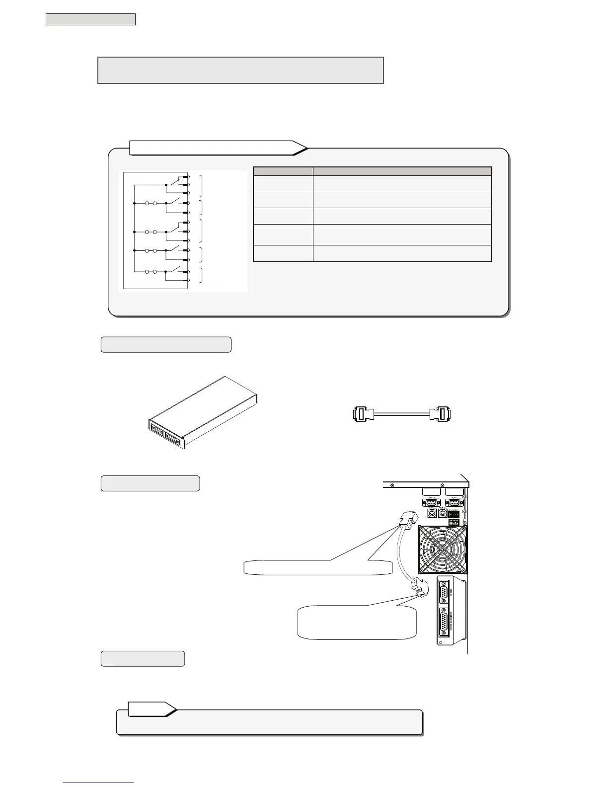
① Insert the contact interface card into the option
card slot on the back panel of the UPS.
② Using the contact interface card communications cable,
connect the “CARD I/F” connector of the UPS to the
“AUX IN” connector of the contact interface card.
You can set the Interface setting to either “Workstation” or “Standalone”. The card operates under both
settings.
The contact interface card and LAN interface card cannot be used simultaneously.
Note
Equipment you will need
Connection procedure
User settings
(Supplied with contact
interface card)
The following signals are output.
Signal name Description
AC input error
This signal is output on a utility power outage or voltage
error (a contact, b contact).
Battery voltage
low
This signal is output when the battery voltage drops
below the specified level (a contact).
AC output
This signal is output when the UPS is supply AC power
output to the load devices (a contact, b contact).
Bypass output
This signal is output when the UPS is supplying bypass
power to load devices (a contact).
UPS alarm
This signal is output when a alarm condition occurs in
the UPS main unit (a contact).
• All signals are output as no-voltage contact. Contact capacity is AC110V/DC24V
0.2A.
• Make short-pin settings for JP1A to JP1D according to the intended application
of the contact signals.
(When the unit is shipped from the factory, all short pins are inserted and set to
common ground.)
Battery low
Bypass output
 Loading...