Characteristics
64
§
§
1
1
9
9
.
.
3
3
P
P
r
r
o
o
t
t
e
e
c
c
t
t
i
i
v
v
e
e
F
F
u
u
n
n
c
c
t
t
i
i
o
o
n
n
T
T
a
a
b
b
l
l
e
e
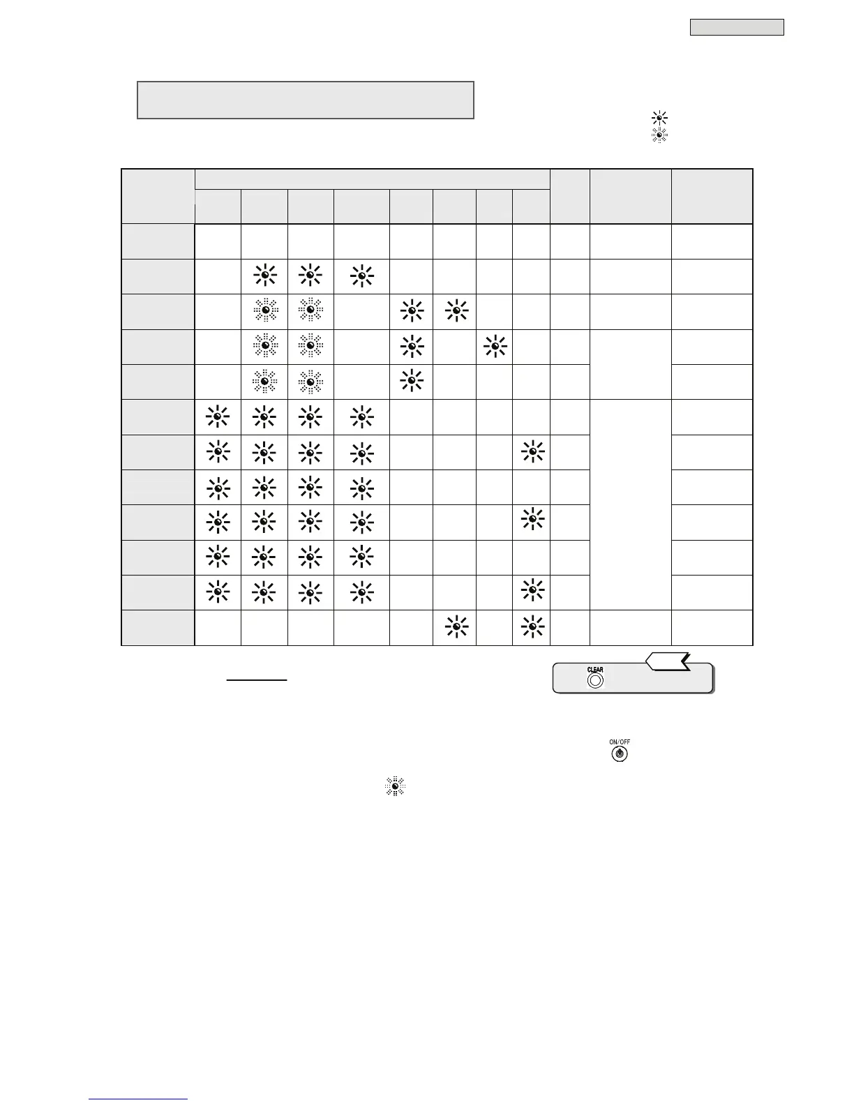
The following table shows functions and operations which activate to protect the UPS.
Control panel (front panel) indicators
Item
Orange
BACK UP
Green
OUTPUT
Green
ON/OFF
Green
INVERTER
Red
BYPASS
Red
ALARM
Red
O.L
Red
BATT.
LOW
Alarms
Buzzer
(*1)
Protective
functions
(UPS operations)
Notes
Preparation
-
(*2) (*2)
- - - - - -
Rectifier, charger,
operation
Power up
Normal
-
- - - - -
Inverter operation
Power up,
operation
Serious failure
-
-
- -
①
Stop inverter
Bypass supply
Overload
(effective value)
-
-
-
-
④
Auto return
Forced bypass
-
- - - - -
Bypass supply
Manual switch
to bypass supply
Input over
voltage
- - - -
②
Battery operation
Input over
voltage
(prolonged)
- - -
③
Battery operation
(*3)
Power outage
- - - -
②
Battery operation
Power outage
(prolonged)
- - -
③
Battery operation
(*3)
Input error
(frequency)
- - - -
②
Battery operation
Input error
(prolonged)
- - -
③
Stop rectifier and
charger
Inverter operation
Battery operation
(*3)
Battery failure
- - - - -
-
①
Stop inverter
Bypass supply
(*1): Buzzer sound patterns:
① * Continuous tone
② **......**......
③ **********...... Continuous beeps
④ ****......****...
(*2): In this state, the LED blinks or is off, depending on the setting of “UPS Operation at
OFF” in the user
setting menu.
When this setting is set to “Bypass” :
When this setting is set to “OFF” : -
(*3): Battery operation. Stops inverter operation when final battery discharge is reached.
Press to stop the buzzer.
Tip
Lit LED :
Blinking LED :
Buzzer Alarm :
①
-
④
Indication of the marks in the table are as follows.
 Loading...