Safety, Operation and Maintenance Manual-September 30, 2019
3-39
3.11 Left and Right Operation Handle
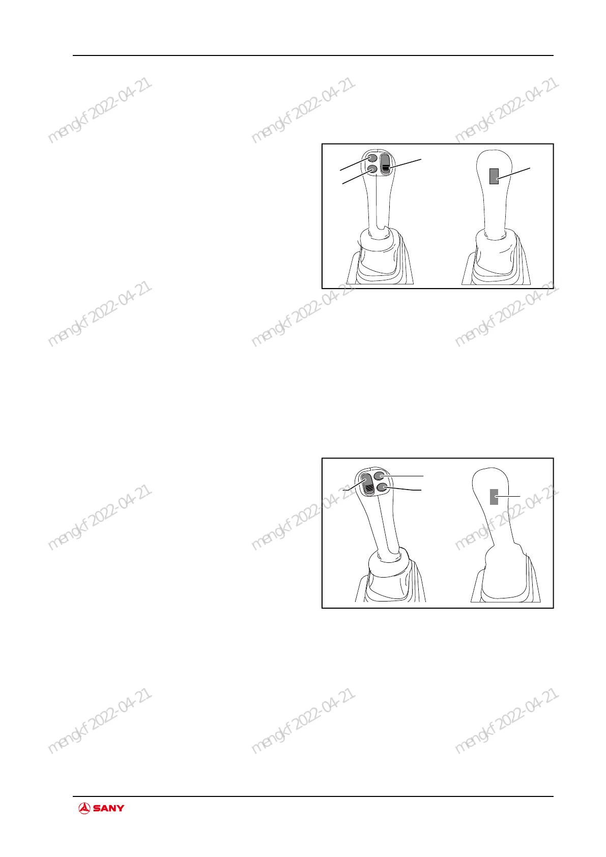
3.11.1 Left operation handle
Fig.3-44 Left Handle Diagram
A. Swing/backup
button
B. Main winch/auxili-
ary winch switchover
button
C. Main winch high
speed button
D. Horn button
PWM button A: Push upward to activate swing
and pull downward for backup.
Button B: Main winch/auxiliary winch
switchover
Button C : Main winch high speed
Button D: Horn
3.11.2 Right operation handle
Fig.3-45 Right Handle Diagram
E. Freefall/high
crowd speed switch-
over button
F. Crowding/derrick-
ing switchover button
G. Engine powerful
gear button
H. Auto shaking of
drilling debirs button
(backup)
PWM button E: Push upward to activate free-
fall. Pull downward to activate high crowd
speed.
Button F: Crowding/derricking switchover
Button G: Engine powerful gear
Button H: Auto shaking of drilling debirs
(backup)
SR400R Rotary Drilling Rig
System Function
mengkf 2022-04-21
mengkf 2022-04-21
mengkf 2022-04-21
mengkf 2022-04-21
mengkf 2022-04-21
mengkf 2022-04-21
mengkf 2022-04-21
mengkf 2022-04-21
mengkf 2022-04-21
mengkf 2022-04-21
mengkf 2022-04-21
mengkf 2022-04-21