1
1-91
8
8
57
60
42
49
111
586
30
77
22
39
940
A
18
410
10
20
380
26
290
105 219 75 75
170 660 110
13
60
34040
13
B
R30
5.5
62 49
67 7.5
63 80
58
6149
340
7
59
60
3
33
52
46
65
121
43
42
49
111
30
77
85 64
22
60
1526
25
8
5
6
8
4
7
5
6
8
4
1
2
3
4
5
6
7
7
Of the 4 o32 holes , use 1 of the 2 holes specified
for drain use to install the port.
Use rubber plugs to seal the remaining 3 holes.
2 x o32 holes (holes for drain)
1
2
3
4
5
6
7
8
Electrical wiring port (o38)
Refrigerant tubing port
Mounting hole (4-R6.5),
anchor bolt : M10
Electrical wiring port (o29)
Electrical wiring port (o19)
Electrical wiring port (o16)
Refrigerant tubing (gas tube),
flared connection (o19.05)
Refrigerant tubing (liquid tube),
flared connection (o12.7)
Unit:mm
Air
intake
Air
intake
Air discharge
Air
discharge
Anchor bolt
Anchor bolt
Air intake
Refrigerant tubing connection portBottom removable connection port
VIEW A
Anchor bolt
Anchor bolt
VIEW B
Anchor bolt
1-4. Dimensional Data
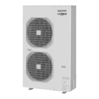
(B) Outdoor Unit: SPW-C906VH8
Remark:
There are two types of supplied tubings.
The one tubing port o19.05 (flare process) is
connected to the flared connection of the gas
port side's service valve. The other "L" shaped
tubing port is brazed in connection after cutting
the tube at the proper length. Then make a
brazing connection to the main tubing (o25.4).
Name Figure Q’ty
Reducing Joint Tube
(o19.05 o25.4)
1
Joint Tube (o19.05)
1
SM830161Book.indb91SM830161Book.indb91 2008/06/039:08:052008/06/039:08:05

 Loading...


