CD ADJUSTMENT
Electrical Adjustment
10K
T;; ~“
So
far we have presented explanations regarding compact
disc player handling, notes prior to repair, handling the pick-
up and disassembly of the unit. Be sure to carefully read
,,43:’]”..’’’.-’.0. ‘
these instructions before making any adjustments.
BAND PASS FILTER
Preparations for Adjustments
Measuring instruments, tools and filter
(4)
AF oscillator (400 Hz, 300mV RMS)
(1) Test disc. : YEDS 18 (Sony)
(5) Frequency Counter (5 MHz ; or more)
(2) Oscilloscope : SS5711 (1OMHZ or dual phenomenon)
(6) Screw drivers
(non metalic) for adjustments
or Memory scope : DSS6521 (Storage scope)
(7) Band Pass Filter (See fugere)
(3) Digital voltmeter (Input impedance 1M ohm
or more)
(8)AC Voltage Meter
Notes :a. The adjustments can be using the equipment produced by other manufactures provided that the performance of
that equipment corresponds to that of the above listed models.
b. Use a 10:1 probe for observing signals on the
oscilloscope and storage scope.
c.
Test disc is subject change without notice.
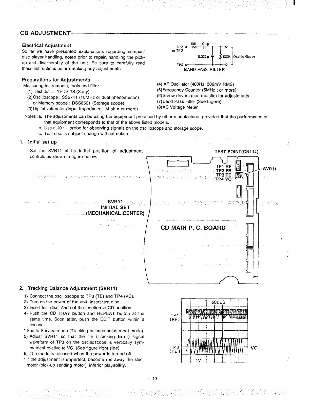
1. Initial
set up
Set the SVR11 at its initial position of adjustment
TEST POINT(CN114)
controls as shown in
figure below.
..... . .. .. -..,.. . . . . . . . .. .. ..
.’ ...,.
,.. .
~~ =WSVR1’
I
II”
Ii
... SVRI1 ... ,“..”- .: : _ ~ ,, -, ,,. ,; - .:7 --.,,;;,
INITIAL SET “
. .._.(MECHANICAL .CENTER) / .
WI
/ ~~
‘----- ------ --- -----—-
1
CD MAIN P. C. BOARD
““[’
[
.-
1,
.
...
.,
\
2. Tracking Balance Adjustment (SVR11)
1) Connect the oscilloscope to TP3 (TE) and TP4 (VC).
2) Turn on the
power of the unit. Insert test disc .
3) Insert test disc. And set the function to CD position.
4) Push the CD TRAY button and REPEAT button at the
TP1
same time. Soon after, push the EDIT button within a
(RF)
second.
‘ See to Service
mode (Tracking balance adjustment mode)
5) Adjust SVR11 so that the
TE (Tracking Error) signal
waveform of TP3 on the oscilloscope is vertically sym-
metrical relative to VC. (See figure right side)
TP3
6) The
mode is released when the power is turned off.
(TE)
‘ If the adjustment is imperfect, become run away the sled
motor (pick-up sending motor), inferior playability.
-17-
Vc
.
..’....
. ...’...........:., .-
 Loading...