CD ADJUSTMENT
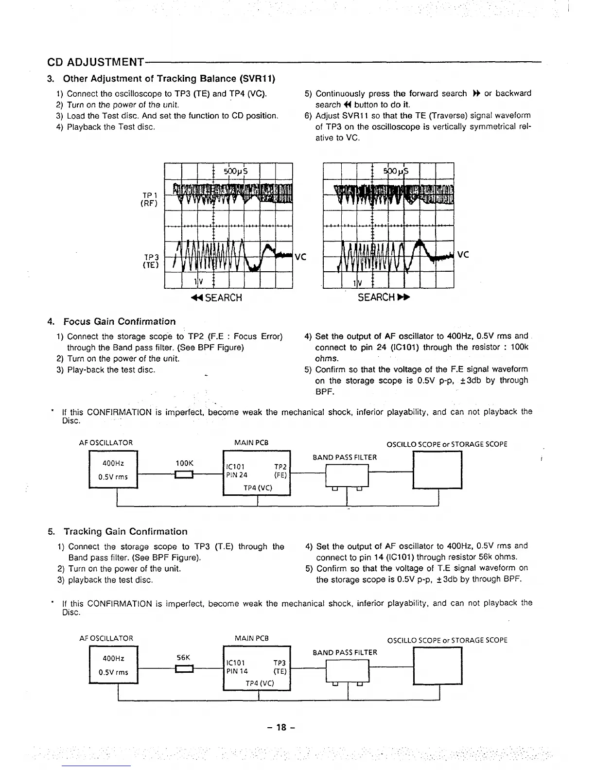
3. Other Adjustment of Tracking Balance (SVRll)
1) Connect the oscilloscope to TP3 (TE) and TP4 (VC). 5) Continuously press the forward search M or backward
2) Turn on the power of the unit.
search 44 button to do it.
3) Load the Test disc. And set the function to CD position.
6) Adjust SVR11 so that the
TE (Traverse) signal waveform
4) Playback the Test disc. of TP3 on the oscilloscope
is vertically symmetrical rel-
ative to VC.
TP 1
(RF)
TP3
(TE)
44 SEARCH
4. Focus Gain Confirmation
Vc
Vc
SEARCH W
1) Connect the storage scope to TP2 (F.E : Focus Error)
4) Set the output of AF oscillator to 400 Hz, 0.5V rms and
through the Band pass filter. (See BPF
Figure)
connect to pin
24 (ICI 01) through the resistor : 10Ok
2) Turn on the power of the unit. ohms.
3) Play-back the test disc.
“ If this CONFIRMATION is
Disc.
AF OSCILLATOR
5) Confirm so that the voltage of the F.E signal waveform
on the storage scope is 0.5V
p-p, t 3db by through
BPF.
,.
imperfect, become weak the mechanical shock, inferior playability, and can not playback the
MAIN PCB
OSCILLO SCOPE or STORAGE SCOPE
,
400Hz
lOOK
BAND PASS FILTER
IClol TP2
0.5V rm5
PIN 24 (FE)
TP4 (VC)
Iuq
I
5. Tracking Gain Confirmation
1) Connect the storage scope to TP3 (T,E) through the
4) Set the output of
AF oscillator to 400 Hz, 0.5V rms and
Band pass filter. (See BPF
Figure).
connect to pin 14
(IC101) through resistor 56k ohms.
2) Turn on the
power of the unit.
5) Confirm so that the voltage of
T.E signal waveform on
3) playback the test disc.
the storage scope is 0.5V p-p, t
3db by through BPF.
● If this CONFIRMATION is imRerfect, become weak the mechanical shock, inferior playability, and can not playback the
Disc.
AF OSCILLATOR
Iclol TP3
PIN 14
(TE)
TP4 (VC)
I
MAIN PCB
OSCILLO SCOPE or STORAGE SCOPE
=
 Loading...