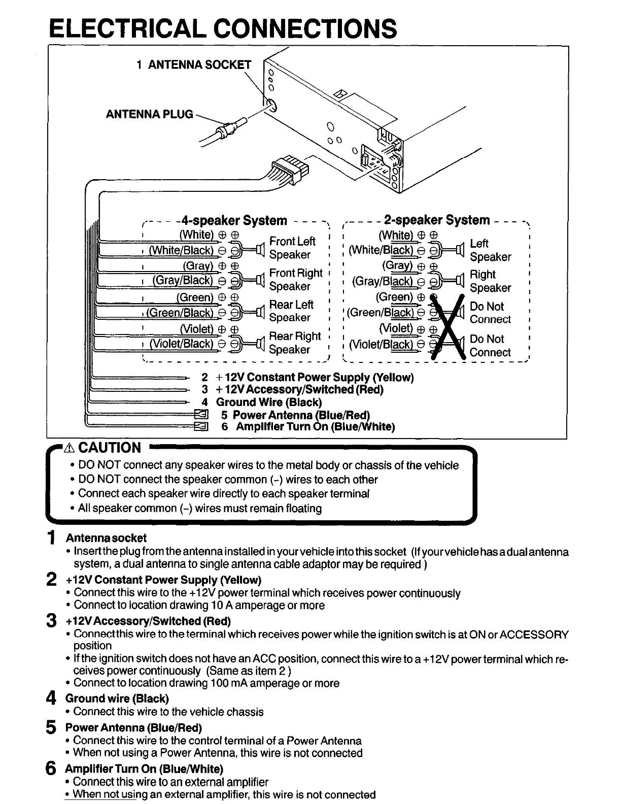
ELECTRICAL CONNECTIONS
I-- -
- - P-speaker System - - -
I
(Ga
: (Gray/Bl&
0
(Green)
i (Green/Bw
I
(vi-
i (Violet/Black)B
\ - - - - - - - -
+ 12V Constant Power Supply (Yellow)
3 -I- 12VAccessoryDwitched (Red)
4 Ground Wire (Black)
5 Power Antenna (Blue/Red)
6 Amplifier Turn On (BluejWhite)
Left
Speaker
Right
Speaker
Do Not
Connect
Do Not
Connect
-----
-\
-2’
l
DO NOT connect any speaker wires to the metal body or chassis of the vehicle
l
Connect each speaker wire directly to each speaker terminal
l
All speaker common (-) wires must remain floating
1 Antenna socket
l
lnserttheplugfromtheantennainstallecl in yourvehicleintothissocket (Ifyourvehiclehasadualantenna
system, a dual antenna to single antenna cable adaptor may be required )
2 +12V Constant Power Supply (Yellow)
l
Connect this wire to the +12V power terminal which receives power continuously
l
Connect to location drawing 10 A amperage or more
3 +12VAccessory/Switched (Red)
l
Connectthis wire to the terminal which receives power while the ignition switch is at ON or ACCESSORY
position
l
If the ignition switch does not have an ACC position, connect this wire to a +12V power terminal which re-
ceives power continuously (Same as item 2 )
l
Connect to location drawing 100 mA amperage or more
4 Ground wire (Black)
l
Connect this wire to the vehicle chassis
5 Power Antenna (Blue/Red)
l
Connect this wire to the control terminal of a Power Antenna
l
When not using a Power Antenna, this wire is not connected
6 Amplifier Turn On (Blue/White)
l
Connect this wire to an external amplifier
l
When not using an external amplifier, this wire is not connected