-13-
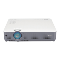
Note:
When remove the Optical unit upward, do not
having projection lens.
Remove 10 screws-A, 4 screws-B and remove
the Optical unit upward.
6.
Optical unit removal.
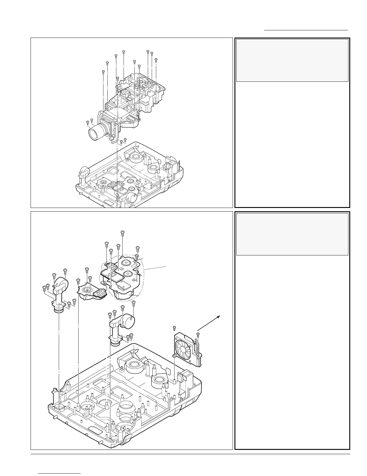
Note :
Mark the Fans as they are
removed from the cabinet bottom
so that they may be reassembled
in the same location from which
they were removed.
Be careful of the attachment
direction of Fan(FN906).
See arrow mark in a figure.
1. Remove 6 screws-A and remove the
adjustable-foot-left.
2. Remove 6 screws-B and remove the
adjustable-foot-right.
3. Remove 3 screws-C and remove the Fan
( FN903 ).
4. Remove 6 screws-D and remove the Fan
unit ( FN904 ,905, 916).
5. Remove 2 screws-E and remove the Fan
( FN906 ).
7.
Fans( FN903, FN904, FN905,
FN906, Fn916 ), and
Adjustable-feet removal.
 Loading...