7-2
Fan Units removal and disassemblies.
Fan(R) Unit removal and Disassemblies.
1. Remove 3 screws-A and remove the Fan(R) Unit.
2. Remove 2 screws-B and remove the Duct-A.
3. Remove 2 screws-C and remove the Fan(FN903).
(See Fig. 7-2, 7-2a)
Fans(G,B) UNIT removal and Disassemblies.
4. Remove 4 screws-D and remove the Fan (G,B) Unit.
5. Remove 6 screws-F and remove the Duct-C.
6. Remove screw-G and remove the Sensor Board.
7. Remove 2 screws-H and remove the Fan (FN905).
8. Remove 2 screws-I and remove the Fan (FN916).
9. Remove 2 screws-J and remove the Fan (FN904).
10. Remove 2 screws-L and remove the RGB IN Fan net
Board.
(See Fig. 7-2, 7-2b)
Note :
Mark the Fans as they are removed from the duct so
that they may be reassembled in the same location
from which they were removed.
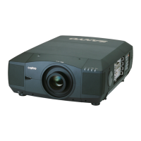
Fig 7-2
Fig.7-2b
Fig.7-2a
Mechanical Disassemblies

 Loading...