-12-
Maintenance
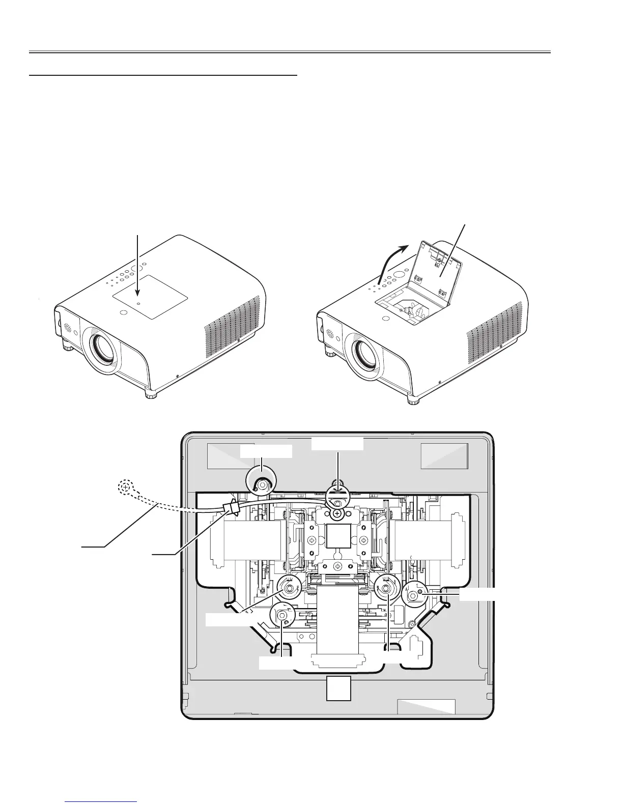
Screw-A
Prism cover panel
This projector provides a prism cover on the cabinet top to enhance the service maintenance. This enables service
personnel to align the optical adjustment or replace the optical parts without disassembly the cabinet top.
1. Loosen 1 screw-A and open the prism cover panel.
2. To remove the LCD Panel/Prism ass'y, loosen 3 screws-B and disonnect a socket-D, and then pull the LCD Panel/
Prism ass'y up.
3. To remove the Optical filter ass'y, remove a screw-C on each stopper of the Optical filter ass'y and then pull the
Optical filter ass'y up.
Screw-B
Screw-C
Screw-B
Screw-B
Screw-C
Screw-C
L
L
Maintenance
Quick maintenance
Socket-D
Grounding
wire

 Loading...