54
Pin Assignment Charts
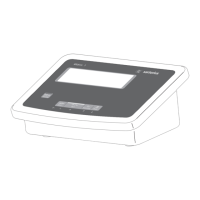
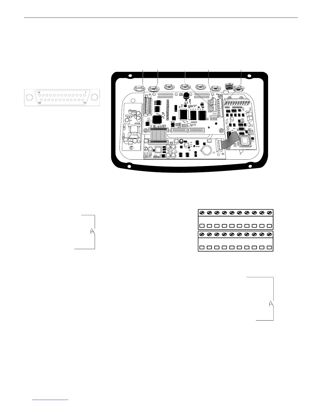
Model CISL3 (IP44 Protection)
COM1 and COM2 female connectors:
25-contact D-Submini female connector
(DB25S) with screw lock hardware
Front view
Male interface connector used
(please use connectors with the same
specifications):
25-pin D-Submini (DB25) with integrated
shielded cable clamp assembly (Amp type
826 985-1C) and fastening screws (Amp
type 164868-1)
Pin assignments COM1 (RS-232)
Pin 1: Shield
Pin 2: Data output (TxD)
Pin 3: Data input (RxD)
Pin 4: Not connected
Pin 5: Clear to send (CTS)
Pin 6: Internally connected
Pin 7: Internal ground (GND)
Pin 8: Internal ground (GND)
Pin 9: Not connected
Pin 10: Not connected
Pin 11: +12 V for printer
Pin 12: RES_OUT\
Pin 13: +5 V
Pin 14: Internal ground (GND)
Pin 15: Universal switch
Pin 16: Control output “lighter”
Pin 17: Control output “equal”
Pin 18: Control output “heavier”
Pin 19: Control output “set”
Pin 20: Data terminal ready (DTR)
Pin 21: Supply ground (GND)
Pin 22: Not connected
Pin 23: Not connected
Pin 24: Power supply +15...25 V
(peripherals)
Pin 25: +5 V
Pin assignments, COM2: RS-232,
RS-422 or RS-485 (optional UniCOM
interface not installed)
Option A11: RS-232 factory set,
Option A12: RS-485 factory set,
RS-422: see “Setting the Interface
Operating Mode for COM2” below
for details on solder bridge coding.
Pin 1: Shield
Pin 2: RS-232: Data output (TxD)
RS-422: Data output (TxD)
RS-485: Data + (TxD-RxD+)
Pin 3: RS-232: Data input (RxD),
RS-422: Data input + (RxD),
RS-485: Not connected
Pin 4: Internal ground (GND)
Pin 5: RS-232: Clear to send (CTS),
RS-422: Data input - (RxD-),
RS-485: Not connected
Pin 6: Internally connected
Pin 7: Internal ground (GND)
Pin 8: Not connected
Pin 9: Not connected
Pin 10: Not connected
Pin 11: +12 V for printer
Pin 12: RES_OUT\
Pin 13: +5 V switch
Pin 14: Internal ground (GND)
Pin 15: Keyboard data
Pin 16: Not connected
Pin 17: Not connected
Pin 18: Not connected
Pin 19: Keyboard clock
Pin 20: RS-232: Data terminal ready
(DTR),
RS-422: Data output - (TxD-),
RS-485: Data - (TxD-RxD-)
Pin 21: LINE_1 _GND
Pin 22: LOW_BATT
Pin 23: BATT_ON_OFF
Pin 24: LINE_1_B
Pin 25: +5 V
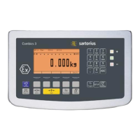
Model CIS3 (IP67 Protection)
Connecting open cable ends to terminal
screws inside the indicator
Com1 interface connection:
Top view
Terminal assignments
No. 1: Universal switch
No. 2: Control output “set”
No. 3: Control output “heavier”
No. 4: Control output “equal”
No. 5: Control output “lighter”
No. 6: Clear to send (CTS)
No. 7: Data output (TxD)
No. 8: Data input (RxD)
No. 9: Data terminal ready (DTR)
No. 10: Internal ground (GND)
No. 11: LINE_A
No. 12: LINE_A
No. 13: GND_LINE_A
No. 14: GND_LINE_A
No. 15: +12 V for printer
No. 16: Reset output
No. 17: +5 V
No. 18: +5 V
No. 19: Ground (GND)
No. 20: Ground (GND)