EasyManua.ls Logo

Sartorius Combics 3 CAIS3 - User Manual

Sartorius Combics 3 CAIS3
130 pages
To Next Page IconTo Next Page
Loading...
98648-018-29
Operating Instructions
Sartorius Combics 3
Models CAISL3 | CAIS3
Indicators

Table of Contents

Question and Answer IconNeed help?

Do you have a question about the Sartorius Combics 3 CAIS3 and is the answer not in the manual?

Sartorius Combics 3 CAIS3 Specifications

General IconGeneral
BrandSartorius
ModelCombics 3 CAIS3
CategoryAccessories
LanguageEnglish

Summary

Warnings and Safety Instructions

General Safety and Installation Guidelines

Essential safety guidelines for operation, installation, and environmental considerations.

Device Description and Intended Use

Combics 3 Features and Design

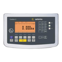
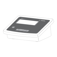
Overview of the indicator's robust design, user interface, and key features.

Equipment Overview

Display and Keypad Layout

Detailed illustration and labeling of the indicator's display and keypad functions.

Back Panel Connections

Identification and description of connectors and ports on the rear panel.

Getting Started and Cable Connections

Initial Setup Steps and WP1 Platform Connection

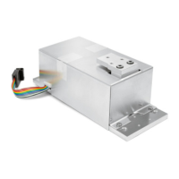
Steps for connecting the platform, configuring ADC, and installing interface cables.

Weighing Platform and Cable Management

Connecting Weighing Platforms (WP2)

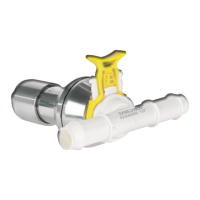
Instructions for connecting IS weighing platforms to the WP2 connection.

Interface Pin Assignments

Digital PCB Pin Assignments (COM, PS2, A8)

Pin assignment details for COM1, COM2, PS2, and A8 interfaces on the digital PCB.

IS Platform and ADC Interface Pins

Pin configurations for IS platforms (A6/A7) and ADC 10,000e (A20) interfaces.

Interface Pin Assignments - COM1

COM1 Female Connector Pinout

Detailed pinout for the COM1 female connector on the CAISL model.

Connecting PC to COM1

COM1 PC Connection Diagram

Pin assignment details for connecting a PC to the indicator via the COM1 interface.

Interface Pin Assignment Chart COM2

COM2 Female Connector Pinout

Detailed pinout for the COM2 female connector on the CAISL model.

Connecting PC to COM2

COM2 PC Connection Diagram

Pin assignment details for connecting a PC to the indicator via the COM2 interface.

PS2 Interface and Barcode Scanner

PS2 Interface Pin Assignments

Pinout for the PS2 female connector used for keyboard or barcode scanner connections.

Finalizing Setup and Power Connection

Connecting the Device to AC Power

Instructions for connecting the indicator to the power supply, including voltage checks and safety.

Configuring Weighing Platforms

Service Mode Activation and Navigation

How to activate, navigate, and exit the Service mode for configuration and calibration.

Service Mode Setup Overview

Overview of Service Mode Menu Structure

A map of the Service mode setup menu, detailing parameter categories and access.

Device Parameter Configuration (WP1, WP2, COM)

WP1 and WP2 Parameter Settings

Configuration options for weighing platforms WP1 and WP2, including interface and SQmin.

A;D Converter Configuration Menus

ADC Configuration: Standard and Verifiable

Standard and verifiable configuration options for the A/D converter, including ranges and units.

Analog;Digital Converter (ADC) Configuration

ADC Configuration Setup and Parameter Setting

Prerequisites and steps for setting scale interval, capacity, and range modes for ADC configuration.

ADC Configuration Parameters Details

Performing ADC Configuration

ADC Configuration Procedure Steps

Step-by-step guide to configuring ADC settings, including mode and accuracy class selection.

Single-Range Mode Configuration

Saving ADC Configuration and Load Cell Connection

ADC Configuration with Load Cells Connected

Steps after ADC configuration, including calibration and preload settings.

Geographical Data Input Procedures

External Adjustment Process

Initiating External Adjustment and Entering Altitude

Starting the external adjustment process and entering altitude/latitude.

Gravity Input and Calibration Completion

Entering Gravity for Adjustment

Inputting the gravity value and confirming it for external adjustment.

Entering Adjustment and Linearization Weights

Setting Calibration and Linearization Weights

Step-by-step guide to entering the external adjustment weight and linearization weights.

Function Allocation for Calibration;Adjustment Key

Configuring CAL Key Function and Sequence

Setting the CAL key function, sequence, and external adjustment activation.

External Calibration with Factory Weights

Configuration for Factory-Defined Weight

Setting the CAL key function for external calibration using a factory-defined weight.

Performing External Calibration with Default Weight

Step-by-step process for performing external calibration using a default weight.

External Calibration Procedure and Printout

Placing Adjustment Weight and Procedure

Instructions for placing the adjustment weight and the steps involved in calibration/adjustment.

External Calibration with User-Defined Weight

Configuration for User-Defined Weight

Selecting the CAL key function for external adjustment using a user-defined weight.

Performing External Calibration with User Weight

Step-by-step process for performing external calibration with a user-provided weight.

User-Defined Calibration and Internal Calibration

Internal Calibration;Adjustment Procedure

How to perform internal calibration, especially for IS platforms.

Adjustment Without Weights

Procedure for Weightless Adjustment

Step-by-step instructions for performing adjustment without using calibration weights.

Weightless Adjustment Parameter Input

Inputting Load Cell Parameters

Entering nominal capacity, resolution, and sensitivity values for load cells.

Function Allocation for Linearization and Preload

Configuring CAL Key for Linearization;Preload

Steps to allocate linearization and preload functions to the CAL key.

External Linearization with User-Defined Weights

Procedure for User-Defined Linearization

Step-by-step guide to performing external linearization with user-defined weights.

User-Defined Linearization Completion

Operating Design - Weighing Mode

Weighing Mode Key Functions Overview

Explanation of primary and secondary functions of keys in weighing mode.

Display in Weighing Mode

Display Layout and Metrological Data

Overview of the display sections, including measured values and metrological data.

Setting Up Password Protection

Password Protection Procedure

Steps to set up or change the password for device and application parameters.

Password Management

Accessing and Managing Password Settings

How to access password settings, enter/delete passwords, and save changes.

Printing Parameter Settings

Setup Overview and WP1 Parameters

COM1 Data Interface Parameters

COM1 XBPI RS-232 Configuration

COM2 and UniCOM Interface Parameters

Device Parameters: Printout Configuration

Operation - Weighing

Weighing Features and Key Functions

Overview of weighing operations, features like zeroing, taring, and soft key functions.

Weighing Operations and Barcode Input

Device Parameters: Operation Settings

Basic Weighing Procedure

Tare Scale with Empty Container

Step-by-step instructions for taring the scale with an empty container.

Placing Sample and Reading Net Weight

Procedure for placing a sample on the scale and reading the stable net weight.

Weighing with Tare Entry and Printing

Numeric Tare Entry and Result Printing

Entering a known tare weight numerically and printing the results.

Weighing Results and Printout Operations

Weighing with Variable Tare Values

Variable Tare Entry and Printing Results

Entering variable tare weights, printing results, and applying package weights.

Net Weight Reading and Tare Deletion

Calibration and Adjustment

Configuration for Legal Metrology Use

Setting up the indicator for legal metrology use via a switch and protective cap.

Calibration and Adjustment Features

Calibration;Adjustment Options and Key Allocation

Available calibration/adjustment features, including blocking keys and sequence settings.

External Calibration with Default Weights

Preparation for External Calibration

Steps to prepare for external calibration, including setup menu navigation.

Performing External Calibration Procedure

Procedure for starting external calibration and placing the required weight.

External Calibration Results and Printout

Finalizing External Calibration and Printout

Steps to start calibration/adjustment and the resulting GMP-compliant printout.

SQmin Operation and Display Settings

SQmin Configuration in Service Mode

Steps to enter SQmin values for WP1, WP2, and WP3 in Service mode.

SQmin Operation Procedure

Performing SQmin Weighing and Generating Printouts

Steps for weighing with SQmin active, generating printouts, and toggling values.

Data ID Codes Configuration

Using Individual ID Codes

Connection Options for Peripherals and Platforms

Configuring Data Interface as COM Port

Data Output Format Details (16 Characters)

Data Output Format Details (22 Characters)

Data Output Format Codes and Examples

External Keyboard Functions

Configuring Data Interface as Printer Port

Printout Content and GMP Compliance

GMP-Compliant Printouts Setup and Configuration

How to enable and configure GMP-compliant printouts, including headers and footers.

Sample Printouts by Application

Sample Printouts for Classification and Animal Weighing

Sample Printouts: GMP and Calibration

Error Codes and Troubleshooting

Fatal and Temporary Error Code Interpretation

Guide to interpreting error codes, their causes, and solutions for device malfunctions.

Care and Maintenance

Specifications: ADC Scale Interface 2*3000 e (Option A8)

Technical Specifications for Option A8 Interface

Detailed technical specifications for the ADC scale interface 2*3000e.

Specifications: ADC Scale Interface 10,000 e (Option A20)

Technical Specifications for Option A20 Interface

Detailed technical specifications for the ADC scale interface 10,000e.

Declarations of Conformity (CE)

CE Directive Compliance Statements

Declarations of conformity with CE directives related to EMC and low voltage.

Declarations of Conformity (RoHS)

RoHS Compliance Statement

Declaration of conformity with the RoHS directive restricting hazardous substances.

Declaration of Type Conformity

EC Declaration for Non-Automatic Weighing Instruments

Official declaration of conformity to EU directives for non-automatic weighing instruments.

EC Type-Approval Certificate

NMi Type Approval Certificate Details

Certificate details from NMi regarding type approval for non-automatic weighing instruments.

Test Certificate

Physikalisch-Technische Bundesanstalt Test Certificate

Official test certificate issued by PTB for the weighing instrument's compliance.

Plates and Markings (CAI... Type TA)

Plates and Markings - Interface and Supply

Plates and Markings - Internal Components

Appendix: Guide to Verification of Weighing Instruments

Appendix: Verification Guide - Compatibility and Legal Info

Appendix: Passwords

Service Password Access and Management

How to access the device in Service mode using the service password.

General Password Access and Management

Procedure for accessing and managing the general password for device parameters.

Related product manuals